Setup
Note:Determinetheleftandrightsidesofthe
machinefromthenormaloperatingposition.
1
InstallingtheAnti-Siphon
FillReceptacle
Partsneededforthisprocedure:
1
90°tting
1
Quickcoupler
1Hoseadapter
1Fill-receptaclebracket
1
Flange-headbolt(5/16x3/4inch)
1Anti-siphonhose
Procedure
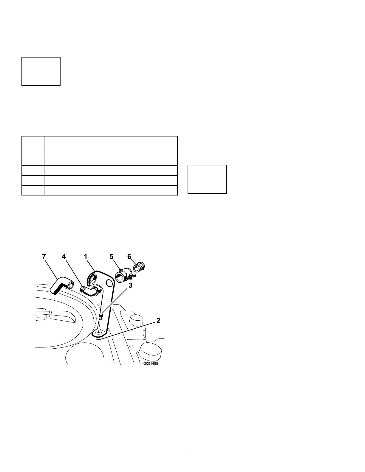
1.Placethell-receptaclebracketoverthe
threadedholeinthetankandsecureitwitha
ange-headbolt(5/16x3/4inch)asshownin
Figure3.
g001488
Figure3
1.Fill-receptaclebracket
5.Quickcoupler
2.Threadedholeinthetank6.Hoseadapter
3.Flangebolt(5/16x3/4
inch)
7.Anti-siphonhose
4.90°elbowtting
2.Placethethreadedendofthe90°elbowtting
throughthebracketandthreadthequickcoupler
ontoit,securingittothebracket(Figure3).
Note:Installthettingwiththeopenend
pointingtowardthelargeopeninginthebracket
andtowardthetankopeningsothatthewater
arcsintothetankwhenyoullit.
3.Installthehoseadapterintothequickcoupler
(Figure3).
4.Locktheadapterintoplacebyswingingthe
leverstowardtheadapterandthensecurethem
withthehairpincotters(Figure3).
5.Installtheanti-siphonhosethroughthelarge
openingonthebracketandontothebarbedend
ofthe90°elbowtting(Figure3).
Important:Donotlengthenthehoseto
allowcontactwiththetankuids.
2
CheckingtheSection-Hinge
Springs
NoPartsRequired
Procedure
Important:Operatingthespraysystemwith
thesection-hingespringsundertheincorrect
compressioncoulddamagetheboomassembly.
Measurethespringsandusethejamnutto
compressthespringsto3.96cm(1.56inches)if
necessary.
Thesprayerisshippedwiththesectionextensions
swungforwardtofacilitateshippingthemachine.
Thespringsarenotfullytightenedatthetimeof
manufacturetoallowthesectionstobeinthisposition
fortransit.Beforeoperatingthemachine,thesprings
mustbeadjustedtothecorrectcompression.
1.Ifnecessary,removethepackingcomponents
thatsecuretherightandleftextensionsections
duringshipping.
2.Supportthesectionswhiletheyareextendedto
thesprayposition.
3.Atthesectionhinge,measurethecompression
oftheupperandlowerspringswhilethesections
areintheirextendedposition(Figure4).
14