Drive System
Maintenance
T orquing the Wheel Lug
Nuts
Service Interval : After the rst hour
After the rst 10 hours
Every 200 hours
Wheel lug nut torque specication: 85 to 90 N∙m
(62 to 66 ft-lb)
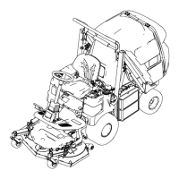
T orque the lug nuts at the front and rear wheels
in a crossing pattern as shown in Figure 68 to the
specied torque.
g459392
Figure 68
Maintaining the Rear Wheel
Alignment
Checking the Rear Wheel
Alignment
Service Interval : Every 200 hours —Check the rear
wheel alignment.
1. Park the machine on a level surface.
2. Disengage the PT O, lower the cutting unit, and
engage the parking brake.
3. Shut of f the engine and remove the key .
4. Rotate the steering wheel so that the rear
wheels are straight ahead.
5. Measure the center-to-center distance at wheel
hub height, in front and in back of the rear tires.
Note: The rear wheels should not toe-in or
toe-out when they are aligned correctly .
6. If the wheels toe-in or toe-out, align the wheels;
refer to Adjusting the Rear Wheel T oe-In ( page
58 ) .
Adjusting the Rear Wheel T oe-In
1. Loosen the jam nuts at both ends of the left and
right tie rods.
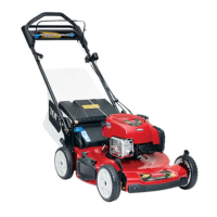
2. Adjust both tie rods until center-to-center
distance at front and back of rear wheels is the
same ( Figure 69 ).
3. When rear wheels are adjusted correctly , tighten
jam nuts against tie rods.
g217458
Figure 69
1. Steering plate 2. Same dimension at front
and rear of wheels
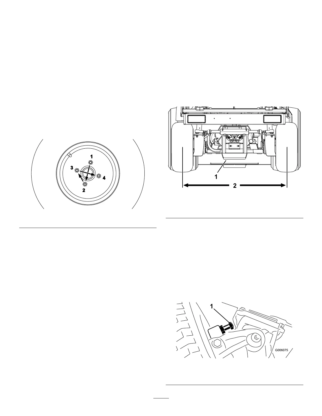
Adjusting Steering Stops
The rear-axle-steering stops help prevent over-travel
of the steering cylinder in case of impact on the rear
wheels. Adjust the stops so that there is 0.23 cm
(0.090 inch) clearance between the bolt head and the
knuckle on the axle when you turn the steering wheel
completely to the left or to the right.
Thread the bolts in or out until you attain a clearance
of 0.23 cm (0.090 inch); refer to Figure 70 .
g006075
Figure 70
1. Steering stop (right side shown)
58