g435855
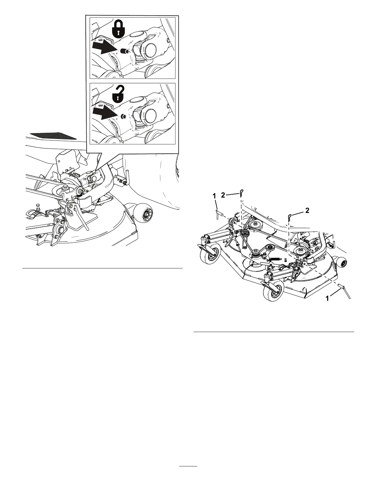
Figure 91
2. Disconnect the forward end of the driveshaft
from the cutting-unit gearbox by pressing the
spring-loaded pin, and then pulling the end of
the driveshaft rearward ( Figure 91 ).
Connecting the Driveshaft
to the Cutting-Unit Gearbox
1. Align the splines of the driveshaft-universal joint
with the splines in the gearbox coupling.
2. Press the spring-loaded pin and then push the
end of the driveshaft forward.
3. Release the spring-loaded pin and check that
the universal joint of the driveshaft is locked into
the cutting-unit gearbox; refer to Figure 91 .
4. Close the universal-joint cover and secure it with
the fastener .
Removing the Cutting Unit
1. Park the machine on a level surface.
2. Disengage the PT O and engage the parking
brake.
3. Before lowering the cutting unit, pull and rotate
the rear link pins at both sides of the cutting unit
( Figure 86 ).
4. Lower the cutting unit and tilt the hopper back.
5. Shut of f the engine and remove the key .
6. T ilt the seat forward.
7. Remove the grass chute; refer to Clearing the
Grass Chute ( page 34 ) .
8. Disconnect the electrical connectors on the right
side of the cutting unit.
9. Disconnect the universal joint of the driveshaft
from the cutting-unit gearbox; refer to
Disconnecting the Driveshaft from the
Cutting-Unit Gearbox ( page 71 ) .
10. Remove the 2 hairpin cotter pins and 2 clevis
pins that secure the lift arms at each side of the
cutting unit ( Figure 92 ).
g435858
Figure 92
1. Clevis pins
2. Hairpin cotter pins
1 1. Roll the cutting unit forward and away from the
traction unit.
Installing the Cutting Unit
1. Park the machine on a level surface.
2. T ilt the hopper back or raise the hopper and
secure it with the magnetic locks in the raised
position.
Shut of f the engine and remove the key .
3. Remove the grass chute; refer to Clearing the
Grass Chute ( page 34 ) .
4. Roll the cutting unit rearward to the traction unit.
72