ReelEngageSwitch
g191000
Figure239
1.Reelengageswitch
2.Controlarm
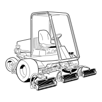
Thereelengageswitchislocatedonthecontrolarm(Figure239)andallowsthe
cuttingunitstooperatewhenthefrontoftheswitchispressed.Anindicatorlight
ontheswitchidentieswhenthereelengageswitchisengaged.
TheTECmonitorsthepositionofthereelengageswitch(upordown).Using
inputsfromtheengageswitchandotherswitchesintheinterlocksystem,the
TECcontrolstheenergizingofthehydraulicsolenoidvalvesusedtodrivethe
cuttingunitmotors.
Note:T oraiseorlowerthecuttingunits,theseathastobeoccupied,themow
speedlimiterhastobeintheMOWposition,andthecuttingunitshavetobe
fullylowered.
TestingtheReelEngageSwitch
1.Parkthemachineonalevelsurface,lowerthecuttingunits,settheparking
brake,andshutofftheengine.
2.Beforeyoudisconnectthereelengageswitchfortesting,ensurethatyoutest
theswitchanditscircuitwiringasaTECelectricalinputwiththeInfoCenter
display;refertoUsingtheInfoCenterDisplayforTroubleshooting(page
7–28).
3.IftheInfoCenterveriesthatthereelengageswitchandcircuitwiringare
functioningcorrectly,nofurtherswitchtestingisnecessary.
4.IftheInfoCenterdeterminesthatthereelengageswitchandcircuitwiring
arenotfunctioningcorrectly,proceedwiththetest.
5.Removethecontrolarmcoverstogetaccesstothereelengageswitch;refer
toDisassemblingtheControlArm(page8–23).
6.EnsurethatthekeyswitchisintheOFFposition.Disconnectthewireharness
electricalconnectorfromthereelengageswitch.
g191001
Figure240
ElectricalSystem:TestingtheElectricalComponents
Page7–66
Reelmaster
®
5410/5510/5610Series
15216SLRevC

 Loading...


