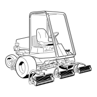
Note:Thedrivecomponentsfortherearrollerbrusharelocatedontheopposite
sideofthecuttingunitfromthecuttingreelhydraulicmotor.Figure357shows
componentsusedwhenthebrushdriveisontheleftsideofthecuttingunit.
Note:TheInstallationInstructionsfortherearrollerbrushkithasdetailed
informationregardingassemblyandadjustment.UsethoseInstructionsalong
withthisServiceManualwhenservicingtherearrollerbrush.
DisassemblingtheRearRollerBrush
1.Parkthemachineonacleanandlevelsurface,lowerthecuttingunits,shut
offtheengine,settheparkingbrake,andremovethekeyfromthekeyswitch.
2.Removetherollerbrushfromthebrushshaftasfollows:
A.Removethenon-drivebrushbearinghousing(item30)fromthecutting
unit.
B.Slidetheexcludersealfromtherollerbrushshaft.
C.RemovethelocknutandJ-boltfrombothendsofthebrush.
D.Whilerotatingthebrush,slidethebrushfromtheshaft.
3.Disassembletherearrollerbrushcomponentsasnecessary.
AssemblingtheRearRollerBrush
g214814
Figure358
1.Rollerbrushshaft
3.Rollerbrush
2.J-bolt4.Locknut
1.Ifbrushwasremovedfromshaft,slidebrushontoshaftwhilerotatingbrush.
Securebrushtoshaftwithtwo(2)J-boltsandlocknuts.Makesurethatthe
J-boltsareinstalledwiththethreadedportionontheoutsideofthebrush.
Tightenthelocknutsfrom2.3to2.8N∙m(20to25in-lb).
CuttingUnit:ServiceandRepairs
Page9–52
Reelmaster
®
5410/5510/5610Series
15216SLRevC

 Loading...


