6
2
3
4
5
6
1
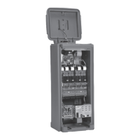
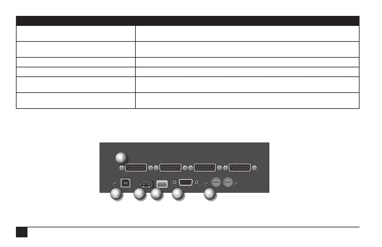
Bottom Ports Purpose
1. Station output ports
(15-pin connectors) (up to four)
These connect to the circuit boards in the Sentinel satellite, controlling up to
12-stations each for a maximum of 48 stations.
2. AC adapter and the red “power on” light LED ashes if a program is running.
The slower the ash, the slower the code is running
3. USB port Allows connecting a thumb drive for “ashing” of the rmware.
4. 2-prong port 24 VAC connection
5. Serial Port 1 (9-pin connector) Both top and bottom serial ports support communications devices, standard off the shelf
serial cables, and are optically isolated.
6. Two fuse sockets with a red LED light next
to each fuse socket
When the red LED is lit, indicates a blown fuse.