5.Removethedrainplugfromthedrainportby
rotatingtheplugcounterclockwiseandremoving
itfromthetransmission(Figure59).
Note:Allowthetransmissionuidtodrain
completely.
6.Installthedrainplug(Figure59).
7.Add700ml(23.7oz)ofDexronVItransmission
uidintothetransmissionthroughthellport
(Figure58).
Note:Useafunnelwithaexiblehosewhen
llingthetransmission.
Note:Whenthetransmissionuidlevelis
correct,theuidshouldbelevelwiththebottom
ofthethreadsinthellport.
8.Installthellplug(Figure58).
ServicingtheReservoirofthe
Speed-ControlCylinder
ServiceInterval:Every200hours
Reservoir-uidtype:DOT3brakeuid
1.Removetheknobsfromthehydraulic-liftlever
andthespeed-rangelever(Figure60).
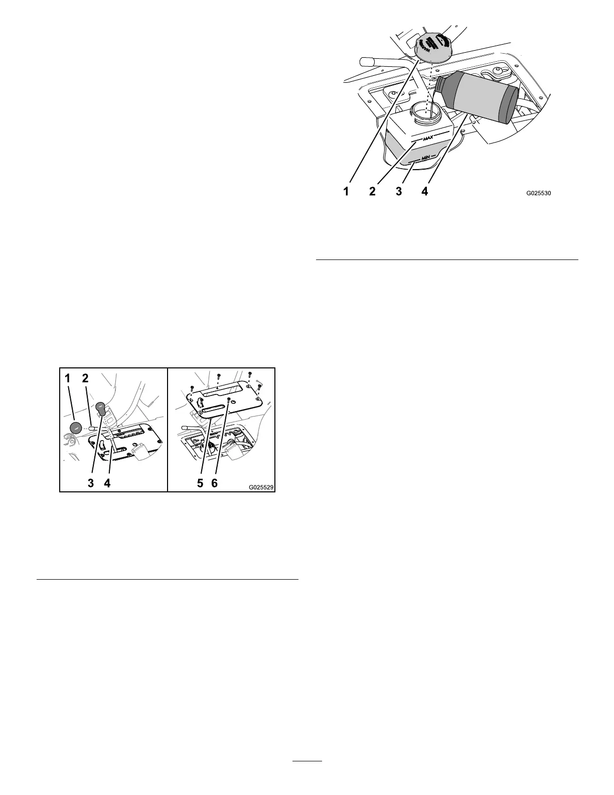
g025529
Figure60
1.Knob(speed-rangelever)4.Rod(hydraulic-liftlever)
2.Rod(speed-rangelever)5.Control-coverplate
3.Knob(hydraulic-liftlever)6.Hex-washerscrews(#10
x3/4inch)
2.Removethe6hex-washerscrews(#10x3/4
inch)thatsecurethecontrol-coverplatetothe
seatbase,andremovethecoverplate(Figure
60).
3.Movethespeed-rangelevertotheTRANSPORT
position;refertoUsingtheSpeed-Range
Control(page27).
4.Checktheuidlevelinthereservoirforthe
speed-controlcylinder(Figure61).
Note:ThenormaluidlevelisbetweentheMin
andMaxmarksonthesideofthereservoir.
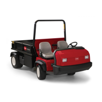
g025530
Figure61
1.Cap3.Minmark(reservoir)
2.Maxmark(reservoir)4.DOT3brakeuid
5.Iftheuidlevelislow,performthefollowing:
A.Wipecleantheareaaroundthecapforthe
reservoir(Figure61).
B.Removethecapfromthereservoir(Figure
61).
C.Addthespecieduidtoraisethelevel
midwaybetweentheMinandMaxmarkson
thesideofthereservoir(Figure61).
D.Installthecaphandtight(Figure61).
6.Aligntheholesinthecontrol-coverplatetothe
holesintheseatbase(Figure60).
7.Securetheplatetothebasewiththe6
hex-washerscrews(Figure60)thatyou
removedinstep2.
8.Threadtheknobsontotherodsforthe
hydraulic-liftleverandthespeed-rangelever
(Figure60).
AdjustingtheSpeedControl
Important:Theminimumcontrolledspeedfor
themachineis4.0kph(2.5mph)atfullengine
speed.Controllingthemachinespeedslowerthat
4.0kph(2.5mph)resultsinexcessivebeltand
clutchwear.
1.DrivethemachineinspeedrangeA(lowrange),
B(mid-lowrange),C(mid-highrange),orD
(highrange)inordertodeterminewhichspeed
rangeincludesthemaximumgroundspeedthat
youwanttoset;refertoUsingtheSpeed-Range
Control(page27).
Note:Usethespeedometertodeterminethe
speedthatthemachineistraveling.
2.Removetheknobsfromthehydraulic-liftlever
andthespeed-rangelever(Figure60).
50