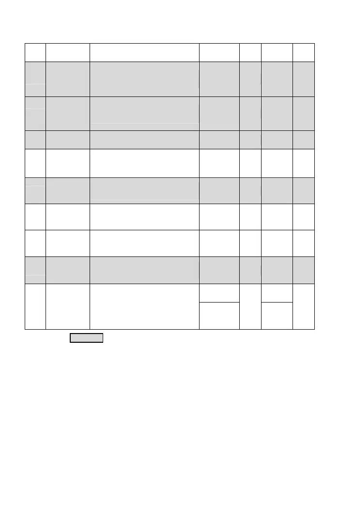
Func. Name Descriptions
Range of
Setting
Unit
Factory
Setting
Note
F3.13
Response
Time of
Automatic
Boost Voltage
Set the response time of automatic
boost voltage range.
1~255 1ms 60
*Note 9
F3.18
Automatic
Voltage
Regulation
(AVR)
0: Disable
1: Enable
0, 1 ─ 1
*Note 9
F3.19
Response
Time of AVR
Set the response time of automatic
voltage regulation.
0~255 1ms 50
*Note 9
F3.21
DC Braking
Level
Set the current level of DC braking
0~150%
of drive
rated current
1% 50
*Note 9
F3.22
DC Braking
Response
Time
djust the response time according
to DC braking.
1~255 1ms 10
*Note 9
F3.23
Time Interval
of DC Braking
at Start
Set the time interval for DC braking
before drive starts.
0.0~60.0 0.1sec 0.0
*Note 9
F3.24
Time Interval
of DC Braking
at Stop
Set the time interval for DC braking
at drive stops.
0.0~60.0 0.1sec 0.5
*Note 9
F3.25
DC Braking
Frequency
at Stop
ctive frequency level of DC braking
at stop.
0.1~60.0 0.1Hz 0.5
*Note 9
350~410
*Note 3,4
390
*Note 3,4
F3.27
Active Level
of Dynamic
Brake
Dynamic brake activates when the
DC bus voltage is over the setting.
Function disable setting:
100/200V series: 410
400V series: 820
700~820
*Note 5
1Vdc
780
*Note 5
*Note 9
The color as means functions can be set during the operation.
28