【F5.02】 AI Input Source Selection
a.The settings are listed as below:
0: DC 4~20mA(2-10V)
1: DC 0~20mA(0-10V)
b. Al-GND analog input terminal
(1) Insert JP1 jumper to V position
The range of AI is 0~10V or 2~10V; Range is set by function F5.02
(2) Insert JP1 jumper to I position
The range of AI is 0~20 mA or 4~20mA; Range is set by function F5.02
【F5.03】
“Pot knob” Gain (Analog Input)
The
“Pot knob” gain range setting, and the setting range is 0.00~2.00.
【F5.04】
“Pot knob” Bias (Analog Input)
The
“Pot knob” bias range setting, and the setting range is -1.00~1.00.
【F5.05】 AI Gain (Analog Input)
The AI gain range setting, and the setting range is 0.00~2.00.
【F5.06】 AI Bias (Analog Input)
The AI gain range setting, and the setting range is -1.00~1.00.
a. Analog input terminals:
1. Pot knob
2. AI-GND 4~20mA(2~10V) or 0~20mA(0~10V)
b. Max. frequency command= Max. output frequency x Analog input gain
(F2.32) (F5.03 or F5.05)
c. Freq. bias value= Max. output frequency x Analog input bias
(F2.32) (F5.04 or F5.06)
d. Frequency command:
bias freq.bias) freq. - command freq. (Max.
20mA) (or10V
command Analog
command Freq.
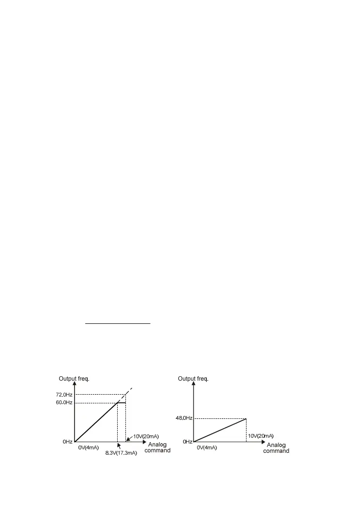
Example:
Analog input bias= 0.00
Max. output frequency= 60.0Hz Max. output frequency= 60.0Hz
Analog input gain= 1.20 Analog input gain= 0.80
65