【F5.25】 Digital Input Response Time
a. Setting the input response time of multi-function terminals (X1~X3) .(digital
debouncing)
b. If the signal length of digital inputs is smaller than the digital input response time,
drive software will reject the input signal and do no process to input signal.
【F5.26】 Multi-function Output Setting of Y1 Terminals
a.Y1:NPN type output terminals.
b.
“+”: Represents a contact (normal open),
“-”: Represents b contact (normal close)
c. Setting the function for output terminals Y1 is listed as below:
±1: Running detection
Detection at drive start
±2: Constant speed detection
Detection at constant speed
±3: Zero speed detection
Detecting at drive zero speed and no detect during the DC braking.
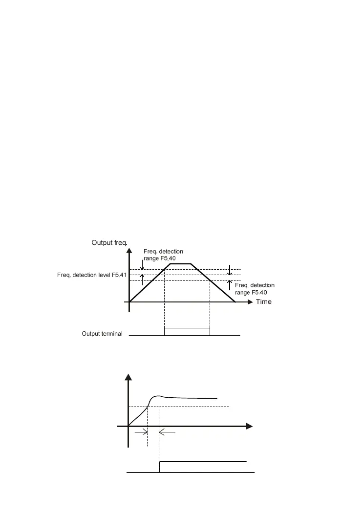
±4: Frequency detection
±5: Overload detection(OLO)
Overload detection
level F4.28(OLO)
Overload detection time
F4.29(OLO)
Output
terminal
Time
Output
current
72