RTHD-SVX01L-EN
17
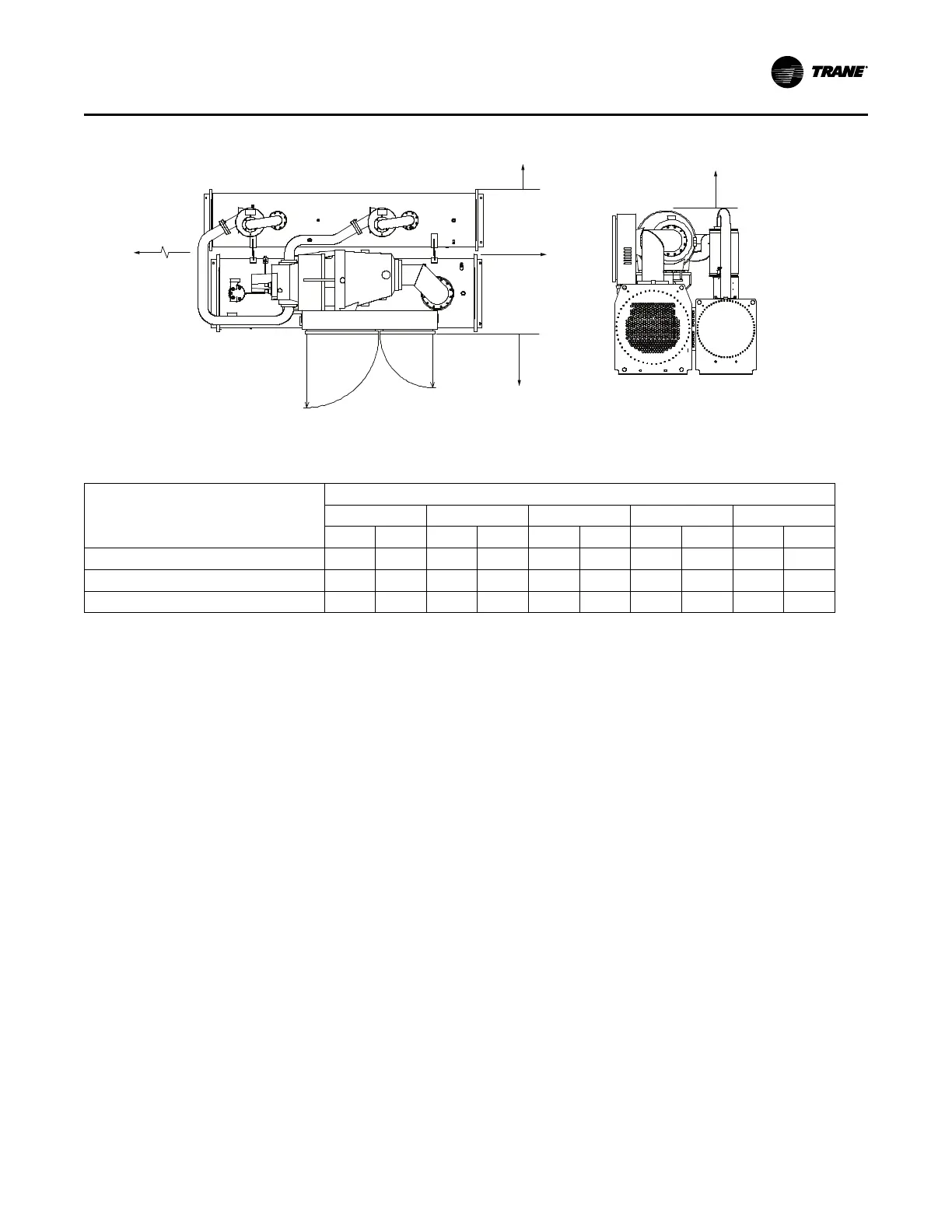
Figure 5. Service clearances
3’-0” (914mm)
Service Clearance
END VIEW
3’-0” (914 mm)
Service Clearance
3’-0” (914mm)
Service Clearance
(Opposite
Tube Removal)
3’-0”
(914mm)
Service
Clearance
26.4” (671mm)
Radius
36.5” (927mm)
Radius
105° Swing
Tube Removal
Clearance
(Either End)
EDE, DDE, CDE, BBB:
108” (2743mm)
EFF, DFF, CEF, BCD:
126” (3200mm)
EGG, DGG, CGG:
130” (3302mm)
TOP VIEW
Note: Optional AFD is not shown.
Table 4. Service clearances
Unit Configuration
(a)
Recommended Clearance
Front Back Either End
Other End
(b)
Top
in mm in mm in mm in mm in mm
BBB,CDE, DDE, EDE
36.5 927 36 914 36 914 108 2743 36 914
EFF, DFF, CEF, BCD
36.5 927 36 914 36 914 126 3200 36 914
EGG, DGG, CGG
36.5 927 36 914 36 914 130 3302 36 914
(a)
Unit configuration digit 1 - compressor code (shown in unit model number digit 6); digit 2 - evaporator code (model number digit 14); digit 3 - condenser code (model number
digit 21).
(b)
Clearance for tube removal.
Dimensions and Weights