RTHD-SVX01L-EN
49
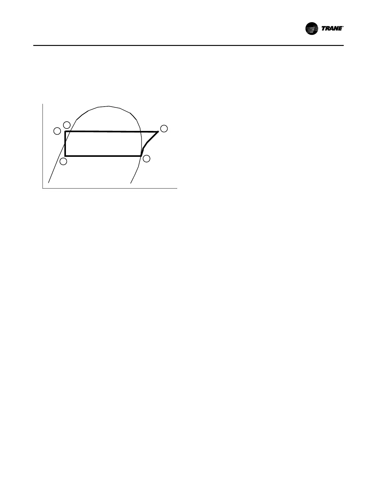
Refrigeration Cycle
The refrigeration cycle can be described using the
pressure-enthalpy diagram shown in Figure 23, p. 49. Key
State Points are indicated on the figure and are referenced
in the discussion following.
Figure 23. Pressure/enthalpy curve
Pressure
Enthalpy
Liquid
1
3
5
2
4
The Optimus™ chiller makes use of a shell-and-tube
evaporator design with refrigerant evaporating on the shell
side and water flowing inside tubes having enhanced
surfaces. Refrigerant vapor leaves the evaporator as
saturated vapor (State Pt. 1).
The refrigerant vapor generated in the evaporator flows to
the suction end of the compressor. The compressor is a
twin-rotor helical rotary type. The refrigerant flows across
the motor, providing the necessary cooling, then enters the
compression chamber. Refrigerant is compressed in the
compressor to discharge pressure conditions.
Simultaneously, lubricant is injected into the compressor.
An oil management system provides an almost oil-free
refrigerant to the shells to maximize heat transfer
performance, while providing lubrication and rotor sealing
to the compressor. The lubrication system ensures long
compressor life and contributes to quiet operation.
Immediately following the compression process the
lubricant and refrigerant are effectively divided using an oil
separator.
The oil-free refrigerant vapor enters the condenser at State
Pt. 2. Condensing is accomplished in a shell-and-tube heat
exchanger where refrigerant is condensed on the shell side
and water flows internally in the tubes. Cooling tower water,
circulating through the condenser tubes, absorbs heat from
this refrigerant and condenses it.
As the refrigerant leaves the bottom of the condenser
(State Pt. 3), it enters an integral subcooler where it is
subcooled before traveling to the electronic expansion
valve (State Pt. 4). The pressure drop created by the
expansion process vaporizes a portion of the liquid
refrigerant.
The resulting mixture of liquid and gaseous refrigerant then
enters the Evaporator Distribution system (State Pt. 5). The
flash gas from the expansion process is internally routed to
compressor suction, and while the liquid refrigerant is
distributed over the tube bundle in the evaporator.
Refrigeration Circuit
Each unit has a single refrigerant circuit that includes
compressor suction and discharge service valves,
removable core filter, charging port, and sight glass. An
electronically controlled expansion valve is provided to
maintain variable capacity modulation over the entire
building load and maintain proper refrigerant flow.
Compressor and Motor
Each RTHD is equipped with a semi-hermetic, direct-drive,
3600 rpm 60 Hz (3000 rpm 50 Hz) rotary compressors that
includes a capacity control slide valve, oil sump heater, and
differential pressure refrigerant oil flow system. The
optional AFD provides additional capacity control with
modulating speed. Four pressure-lubricated rolling element
bearing groups support the rotary assembly. The motor is a
suction gas-cooled, hermetically sealed, two-pole squirrel
cage induction motor.
Evaporator and Condenser
Heat exchangers are shell and tube design. Standard
tubes are externally finned, internally enhanced seamless
copper with lands at all tube sheets. All tube sheets are
made of carbon steel. Tubes are mechanically expanded
into tube sheets and mechanically fastened to tube
supports. Evaporator tubes are 1.0- inch (25.4 mm)
diameter and condenser tubes are 0.75-inch (19.05 mm)
diameter. All tubes can be individually replaced.
Shells are carbon steel plate. The evaporator and
condenser are designed, tested, and stamped in
accordance with ASME Code for refrigerant-side/ working-
side pressure of 200 psig (13.8 bars).
All water pass arrangements are available with grooved
connections (150 or 300 psig waterside working pressure).
All connections may be either right- or left-handed.
Waterside shall be hydrostatically tested at 1.5X design
working pressure.
Oil Management
The unit is configured with an oil management system that
ensures proper oil circulation throughout the unit. The key
components of the system include an oil separator, oil filter,
oil sump and oil sump heater. An optional oil cooler is
installed when the unit is used for high condensing
temperature or low evaporator temperature conditions.
Unit-Mounted Starter
A unit-mounted starter and control panel is provided on
every chiller. The Symbio™ 800 provides for accurate
chilled water control as well as monitoring, protection and
adaptive limit functions. The “adaptive” nature of the
Operating Principles