RTHD-SVX01L-EN
45
External Chilled Water Setpoint - Optional
Symbio 800 will accept either a 2-10 Vdc or a 4-20 mA
input (J9-4, J9-5) signal, to adjust chilled water setpoint
remotely.
External Demand Limit Setpoint - Optional
Symbio 800 will accept either a 2-10Vdc or a 4-20mA input
(J7-11, J7-12) signal to adjust the demand limit setpoint
from a remote location.
Percent Condenser Pressure Output -
Optional
Symbio 800 provides a 2-10 Vdc analog output to indicate
percent High Pressure Cutout (HPC) condenser pressure.
Percent HPC = (Condenser Pressure/High Pressure
Cutout Setpoint)*100
Compressor Percent RLA Output - Optional
Symbio 800 provides a 2-10 Vdc analog output to indicate
%RLA of compressor starter average phase current. The
values of 2 to 10 Vdc correspond to 0 to 120% RLA.
AFD Drive (Optional)
Trane TR200 drive is an electronic motor controller that
converts AC mains input into a variable AC waveform
output. The frequency and voltage of the output are
regulated to control the motor speed or torque.
TR200 drive includes the following features:
• Soft start to minimize inrush current
• Improved harmonic mitigation with DC link reactor
• Integrated power fuse
• Graphical LCD keypad
• Unit Mounted with factory pre-wiring
• ‘Trane Drive Utility’ for configuration and tracking
See Service Manual, BAS-SVM01*-EN, TR200 New D-
Frame for more information.
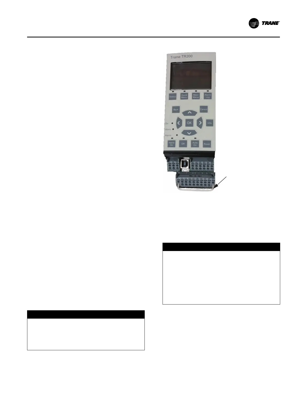
AFD Drive Installation
The AFD drive is manufactured with a jumper installed
between terminal 12 (+24Vdc source) and terminal 37
(Safe Stop digital input). This jumper must be removed
prior to unit operation. See Figure 21, p. 45 for view of
jumper as it would be installed on drive from manufacturer.
NOTICE
Equipment Damage!
Failure to follow instructions below could result in
equipment damage.
Verify/remove jumper between AFD terminals 12 and
37 before unit operation.
Figure 21. AFD jumper
Jumper between
terminals 12 and 37
must be removed
prior to unit
operation.
Important:
• For factory provided AFD units, verify
jumper has been removed.
• For field installed drives, remove jumper
shown in Figure 21, p. 45.
AFD Drive Programming
NOTICE
Equipment Damage!
Changing default clockwise phase rotation or
enabling phase reversal protection could prevent
proper chiller operation or cause equipment damage.
• Do NOT change Adaptive Frequency™ drive
(AFD) phase rotation to counterclockwise.
• Do NOT enable phase reversal protection.
Field replacement drives must be programmed via the
keypad interface. Program non-compressor specific
parameters first in sequential order (), followed by
compressor specific parameters (see Table 14, p. 46) in
sequential order.
Installation Electrical