20
RTHD-SVX01L-EN
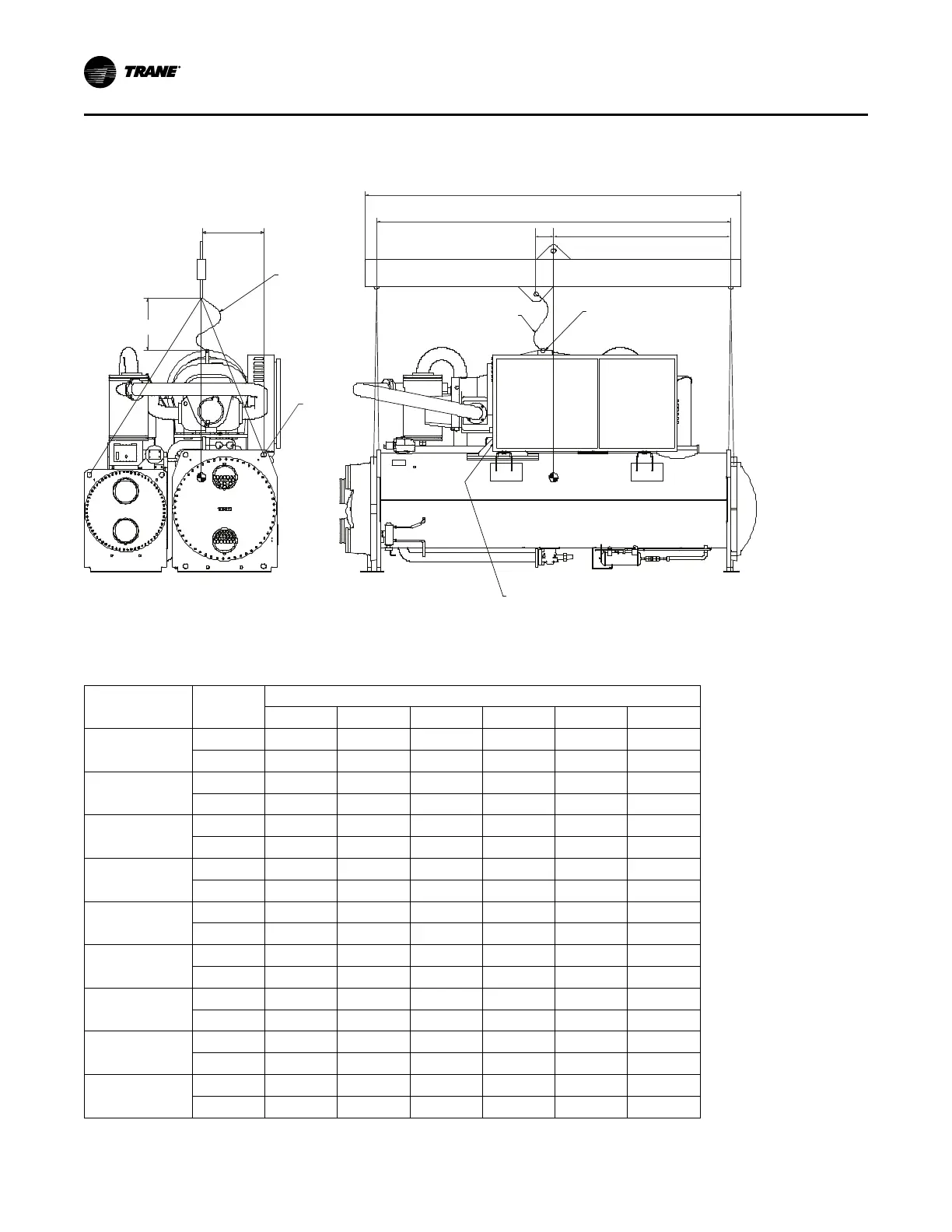
Lifting Procedure
Figure 7. Rigging configuration
Anti-rolling
Cable
F (min)
Evaporator
A
Eyelet or M16
Internal Thread
Lifting
Holes
44.5mm dia typ
Starter
Controls
Anti-rolling
Cable
Condenser
Unit Model Number Location
B
D C
E
Note: Optional AFD is not shown. See Figure 3, p. 11 for location of optional AFD. Rigging information is same for wye-delta or
AFD units.
Table 5. Rigging dimensions
Unit Configuration
(a)
Units
Dimension
A B C D E F
B1B1B1
in 120.00 108.00 56.97 3.92 21.02 24.00
mm 3048 2743 1447 97 534 610
B1C1D1
in 144.00 132.00 58.23 3.74 20.51 24.00
mm 3658 3353 1479 95 521 610
B2B2B2
in 120.00 108.00 58.11 3.86 21.06 24.00
mm 3048 2743 1476 98 535 610
B2C2D2
in 144.00 132.00 58.31 3.66 20.59 24.00
mm 3658 3353 1481 93 523 610
C1D5E4
in 120.00 108.00 59.96 8.62 22.99 24.00
mm 3048 2743 1523 219 584 610
C1D6E5
in 120.00 108.00 60.00 8.58 22.91 24.00
mm 3048 2743 1524 218 582 610
C1E1F1
in 144.00 132.00 63.50 5.08 24.57 24.00
mm 3658 3353 1613 129 624 610
C2D3E3
in 120.00 108.00 59.72 8.86 24.33 24.00
mm 3048 2743 1517 225 618 610
C2D4E4
in 120.00 108.00 59.96 8.62 22.99 24.00
mm 3048 2743 1523 219 584 610
Installation Mechanical