RTHD-SVX01L-EN
39
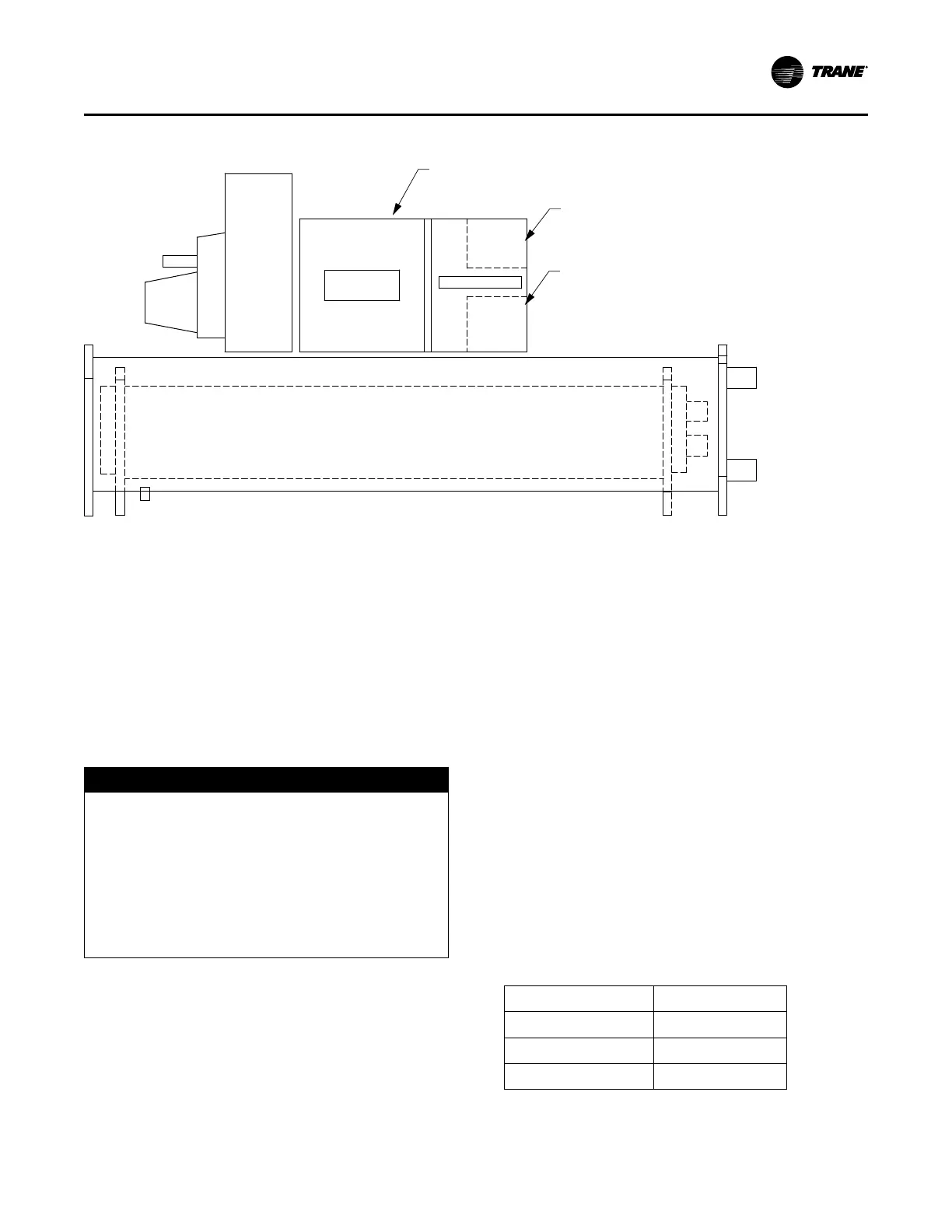
Figure 19. Electrical Installation
6.1” x 14.6” (156x370mm)
opening for incoming line voltage
(8) 1/2” conduit knockout
for use with 30 volt wiring
(6) 1/2” conduit and (4) 1-1/4” conduit
knockouts for use with 115 volts wiring
Class II
30 VAC max
Low Voltage
Area
VFD Drive
Evaporator
Condenser
Line Voltage
and Power
Section
Control Section
Class I
132 VAC max
Control Voltage
Area
Water Pump Power Supply
Provide power supply wiring with fused disconnect for both
the chilled water and condenser water pumps.
Compressor Motor Phase Sequencing
Always verify that proper rotation of the compressor is
established before the machine is started. Proper motor
rotation requires confirmation of the electrical phase
sequence of the power supply. The motor is internally
connected for clockwise rotation with incoming power
supply phased A, B, C.
Units with Optional AFD
NOTICE
Equipment Damage!
Changing default clockwise phase rotation or
enabling phase reversal protection could prevent
proper chiller operation or cause equipment damage.
• Do NOT change Adaptive Frequency™ drive
(AFD) phase rotation to counterclockwise.
• Do NOT enable phase reversal protection.
AFD must be set with phase rotation clockwise (default
from factory), and phase reversal protection DISABLED.
All Units
To confirm the correct phase sequence (ABC), use a Model
45 Associated Research Phase indicator or equivalent.
Voltages generated in each phase of a polyphase
alternator or circuit are called phase voltages. In a three-
phase circuit, three sine wave voltages are generated,
differing in phase by 120 electrical degrees. The order in
which the three voltages of a three-phase system succeed
one another is called phase sequence or phase rotation.
This is determined by the direction of rotation of the
alternator. When rotation is clockwise, phase sequence is
usually called “ABC,” when counterclockwise, “CBA.”
This direction may be reversed outside the alternator by
interchanging any two of the line wires. It is this possible
interchange of wiring that makes a phase sequence
indicator necessary if the operator is to quickly determine
the phase rotation of the motor.
Correcting Improper Electrical Phase Sequence
Proper compressor motor electrical phasing can be quickly
determined and corrected before starting the unit. If using
an Associated Research Model 45 Phase Sequence
Indicator, follow this procedure:
1. Press the STOP button to insure the unit will not
attempt to start the compressor.
2. Open the electrical disconnect or circuit protection
switch that provides line power to the line power
terminal block in the control panel (or to the unit-
mounted disconnect).
3. Connect the phase sequence indicator leads to the line
power terminal block (or the unit mounted disconnect)
as follows:
Phase Seq. Lead
1TB1 Terminal
Black (Phase A)
L1
Red (Phase B)
L2
Yellow (Phase C)
L3
4. Turn power on by closing the unit supply power
disconnect switch.
Installation Electrical