RTHD-SVX01L-EN
23
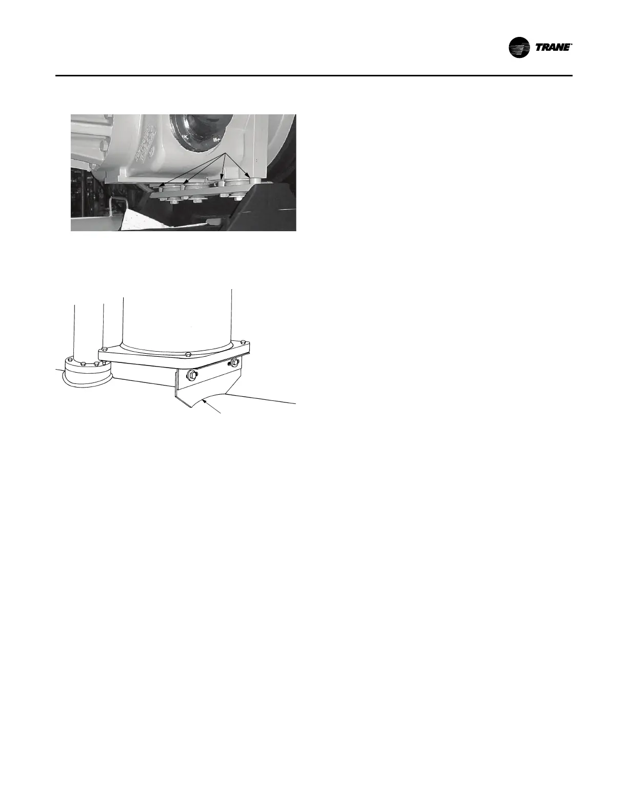
Figure 10. Compressor shipping spacers C, D, E
family (discharge side)
Compressor
Housing
Remove (4)
Puck-Type
Spacers
10. Remove the shipping brackets from the bottom sides of
the oil separator(s). See Figure 11, p. 23.
Figure 11. Oil separator shipping bracket
Notes:
• Once shipping bracket(s) is removed, the oil
separator is only supported by the discharge
line.
• Failure to remove oil separator shipping
brackets could result in excessive noise.
Unit Leveling
Note: The electrical panel side of the unit is designated as
the “front” of the unit.
1. Check unit level end-to-end by placing a level on the
top surface of the evaporator shell.
2. If there is insufficient surface available on the top of
evaporator shell, attach a magnetic level to bottom of
shell to level the unit. Unit should be level to within 1/4
inch (6.35 mm) over its length.
3. Place the level on the evaporator shell tube sheet
support to check side-to-side (front-to-back) level.
Adjust to within 1/4 inch (6.35 mm) of level front-to-
back.
Note: The evaporator MUST be level for optimum heat
transfer and unit performance.
4. Use full-length shims to level the unit.
Alternate Moving Method
If it is not possible to rig from above as shown in , the unit
may also be moved by jacking each end high enough to
move an equipment dolly under each tube sheet support.
Once securely mounted on the dollies, the unit may be
rolled into position.
Alternate Moving Method
If it is not possible to rig from above as shown in , the unit
may also be moved by jacking each end high enough to
move an equipment dolly under each tube sheet support.
Once securely mounted on the dollies, the unit may be
rolled into position.
Isolation Pads
Notes:
• The elastomeric pads shipped (as standard)
are adequate for most installations. For
additional details on isolation practices consult
an acoustical engineer for sound-sensitive
installations.
• Durometer values for isolator pads are a
measure of resilience. See the following figure.
Installation Mechanical