40
RTHD-SVX01L-EN
5. Read the phase sequence on the indicator. The “ABC”
indicator on the face of the phase indicator will glow if
phase is “ABC”.
WARNING
Hazardous Voltage w/Capacitors!
Failure to disconnect power and discharge
capacitors before servicing could result in death
or serious injury.
Disconnect all electric power, including remote
disconnects and discharge all motor start/run
capacitors before servicing. Follow proper
lockout/tagout procedures to ensure the power
cannot be inadvertently energized. For variable
frequency drives or other energy storing
components provided by Trane or others, refer to
the appropriate manufacturer’s literature for
allowable waiting periods for discharge of
capacitors. Verify with a CAT III or IV voltmeter
rated per NFPA 70E that all capacitors have
discharged.
6. If “CBA” indicator glows instead, open unit main power
disconnect and switch two line leads on the line power
terminal block (or the unit mounted disconnect). Re-
close main power disconnect and recheck phasing.
7. Reopen the unit disconnect and disconnect the phase
indicator.
Electrical Connections
Proper starter/control panel line-side lug sizes are specified
on the unit submittals. These lug sizes must be compatible
with conductor sizes specified by the electrical engineer or
contractor.
For recommended field connection lug sizes (RTHD
starters) see unit submittal.
Circuit Breakers and Non-Fused Disconnect
Switches (Factory Installed Option)
Units that are ordered with factory installed circuit breakers
or non-fused disconnect switches ship with the handle in
the control panel. The handle must be installed prior to
starting the unit.
The operating mechanism is already pre-installed on the
Disconnect/ Circuit Breaker frame.
The hole locations and shafts lengths have already been
cut, and the shaft already installed.
WARNING
Hazardous Voltage w/Capacitors!
Failure to disconnect power and discharge capacitors
before servicing could result in death or serious
injury.
Disconnect all electric power, including remote
disconnects and discharge all motor start/run
capacitors before servicing. Follow proper lockout/
tagout procedures to ensure the power cannot be
inadvertently energized. For variable frequency drives
or other energy storing components provided by
Trane or others, refer to the appropriate
manufacturer’s literature for allowable waiting periods
for discharge of capacitors. Verify with a CAT III or IV
voltmeter rated per NFPA 70E that all capacitors have
discharged.
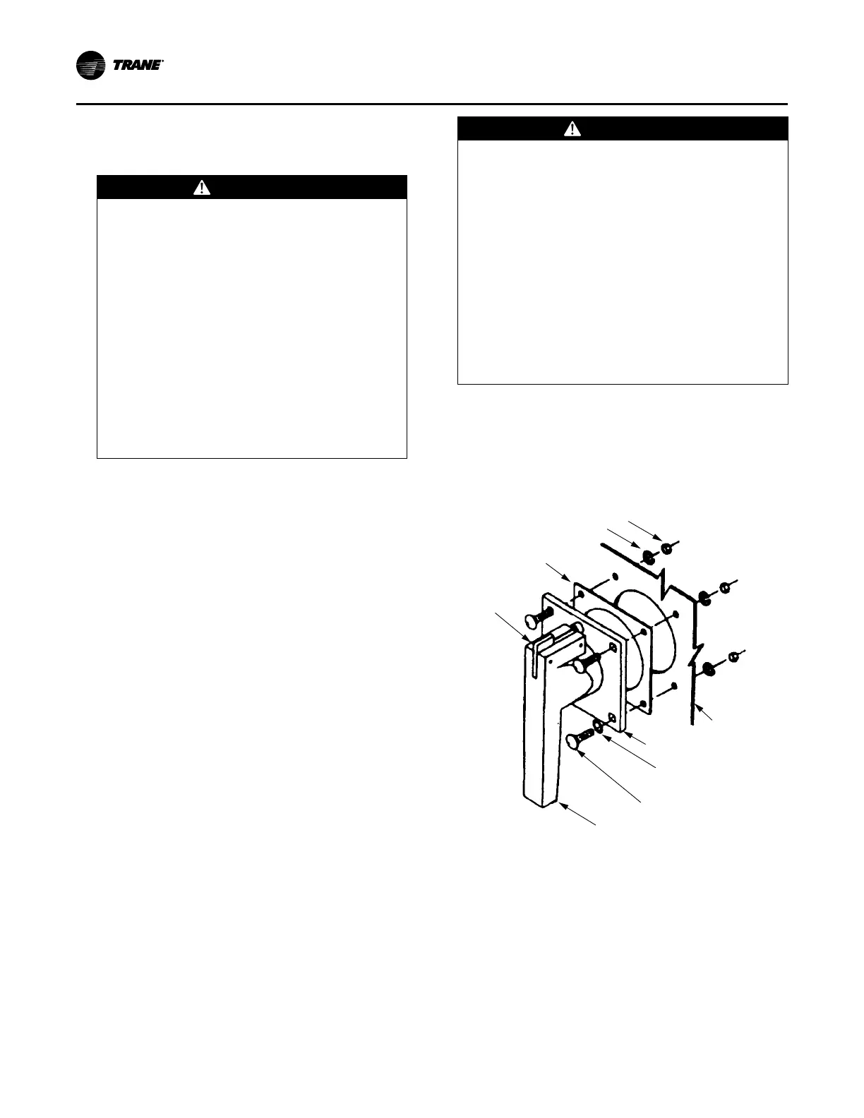
1. Attach the handle and gasket to the enclosure door and
secure with the four bolts, lock washers and nut as
shown in Figure 20, p. 40. Tighten to 75 in-Lbs.
Note: There is an additional Lexan spacer on the handle,
not shown in the Figure 20, p. 40. Do not remove.
Figure 20. Handle on door
1/4” Lockwasher (4)
Gasket
Lock
Plate
1/4-20 Hex Nut (4)
Cut Away of
Enclosure Door
Handle Plate
Sealing Washer (4)
(Used with 4 & 4X
Enclosures Only)
1/4-20 x 1 Square Neck Bolt (4)
Handle
2. Check that when the enclosure door is closed, the
handle interlocks with the shaft in all handle positions
except RESET/OPEN. To open the enclosure door
when the breaker is in the ON position, rotate the screw
slot on the handle plate counter -clockwise. Verify
operation.
Installation Electrical