RTHD-SVX01L-EN
33
NOTICE
Equipment Damage!
Failure to comply with specifications may result in
capacity reduction, unit damage and/or relief valve
damage.
Do NOT exceed vent piping code specifications!
Relief valve discharge setpoints and capacities rates are
given in . Once the relief valve has opened, it will re-close
when pressure is reduced to a safe level.
Note: Once opened, relief valves may have tendency to
leak and must be replaced.
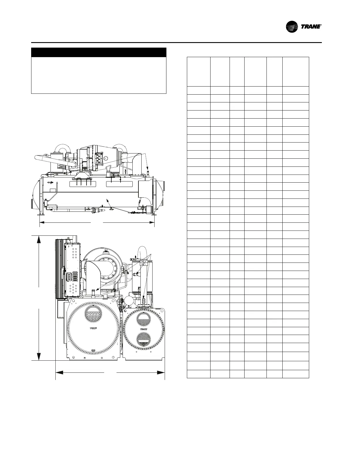
Figure 17. Relief valve location
Relief
Valves
Evaporator Condenser
W
H
Relief Valves
Evaporator
L
Pressure relief valve discharge capacities will vary with
shell diameter and length and also compressor
displacement. Discharge venting capacity should be
calculated as required by ASHRAE Standard 15-94. Do not
adjust relief valve setting in the field.
Table 6. Pressure relief valve data
Valve
Location -
Size
Dis-
charge
Setpoint
(psi)
Num-
ber of
Valves
Rated
Capacity
per Relief
Valve (lba/
min)
Field
Conn
Pipe
Size
(NPT)
Factory
Shell Side
Conn (in)
Evap - B1
200 1 48 1 1-5/16 - 12
Evap - B2
200 1 48 1 1-5/16 - 12
Evap - B3
200 1 48 1 1-5/16 - 12
Evap - C1
200 1 48 1 1-5/16 - 12
Evap - C2
200 1 48 1 1-5/16 - 12
Evap - D1
200 1 48 1 1-5/16 - 12
Evap - D2
200 1 48 1 1-5/16 - 12
Evap - D3
200 1 48 1 1-5/16 - 12
Evap - D4
200 1 48 1 1-5/16 - 12
Evap - D5
200 1 48 1 1-5/16 - 12
Evap - D6
200 1 48 1 1-5/16 - 12
Evap - E1
200 1 48 1 1-5/16 - 12
Evap - F1
200 1 48 1 1-5/16 - 12
Evap - F2
200 1 48 1 1-5/16 - 12
Evap - G1
200 1 78.8 1-1/4 1-5/8 - 12
Evap - G2
200 1 78.8 1-1/4 1-5/8 - 12
Evap - G3
200 1 78.8 1-1/4 1-5/8 - 12
Cond - B1 200 2 48 1 1-5/16 - 12
Cond - B2 200 2 48 1 1-5/16 - 12
Cond - D1 200 2 48 1 1-5/16 - 12
Cond - D2 200 2 48 1 1-5/16 - 12
Cond - E1 200 2 48 1 1-5/16 - 12
Cond - E2 200 2 48 1 1-5/16 - 12
Cond - E3 200 2 48 1 1-5/16 - 12
Cond - E4 200 2 48 1 1-5/16 - 12
Cond - E5 200 2 48 1 1-5/16 - 12
Cond - F1 200 2 48 1 1-5/16 - 12
Cond - F2 200 2 48 1 1-5/16 - 12
Cond - F3 200 2 48 1 1-5/16 - 12
Cond - G1 200 2 48 1 1-5/16 - 12
Cond - G2 200 2 48 1 1-5/16 - 12
Cond - G3 200 2 48 1 1-5/16 - 12
Comp - B1/
B2
(a)
200 2 78.8 1-1/4 1-5/8 - 12
Comp - C1/
C2
(a)
200 3 78.8 1-1/4 1-5/8 - 12
Comp - D1/
D2/D3
(a)
200 3 78.8 1-1/4 1-5/8 - 12
Comp - E3
(a)
200 3 78.8 1-1/4 1-5/8 - 12
(a)
Only used with isolation valve option
Thermal Insulation
All Optimus™ units are available with optional factory
installed thermal insulation. If the unit is not factory
insulated, install insulation over the areas shaded in Figure
Installation Mechanical