22
RTHD-SVX01L-EN
WARNING
Shipping Mounts!
Failure to follow below instructions could result in
death or serious injury or equipment damage.
• Do not use the threaded holes in the compressor
to lift or assist in lifting the unit. They are not intended
for that purpose and could create a dangerous
situation.
• Do not remove the wood mounts until the unit is in
its final location.
NOTICE
Equipment Damage!
Failure to follow instructions below could result in
equipment damage.
• Never use a forklift to move the unit. The skid is
not designed to support the unit at any one
point and using a forklift to move the equipment
may cause unit damage.
• Always position the lifting beam so that cables
do not contact the unit.
Note: If absolutely necessary, the chiller can be pushed or
pulled across a smooth surface if it is bolted to wood
shipping mounts.
1. See Table 2, p. 15 or Table 3, p. 15 for unit shipping
weights.
Note: Weights are typical for units with R-134a or R-513A
charge.
2. When unit is at its final location, remove shipping bolts
that secure unit to wood base mounts.
3. Install clevis connectors in lifting holes provided on the
unit. Attach lifting chains or cables to clevis connectors
as shown in Figure 7, p. 20. Each cable alone must be
strong enough to lift the chiller.
4. Attach cables to lifting beam as shown in Figure 7, p.
20. See Table 5, p. 20 for rigging dimensions. The
lifting beam crossbar must be positioned so the lifting
cables do not contact unit piping or electrical panel
enclosure.
5. Connect an anti-rotation strap or cable loosely between
the lifting beam and the threaded coupling or eyelet
provided at the top of the compressor. Use an eyebolt
or clevis to secure the strap at the coupling or eyelet.
Important: The anti-rotation strap is not a lifting chain, but
a safety device to ensure that the unit cannot
tilt during lifting.
6. Lift from above, or jack the unit per “Alternate Moving
Method,” p. 23. Remove the base mounts.
7. During final positioning of the unit, place the isolation
pads under the evaporator and condenser tube sheet
supports as shown in Figure 12, p. 24. See “Isolation
Pads,” p. 23 for information on isolation pads.
8. Level the unit as described in “Unit Leveling,” p. 23.
9. The unit is shipped with spacers on the compressor
mount that protect isolation pads during shipping and
handling. Before the unit is operated, remove the
spacers as indicated to prevent excessive noise.
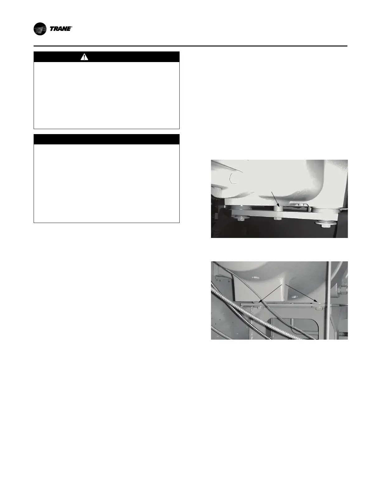
• B Family Compressors:
– Remove qty 1 puck-type spacer under discharge
side of compressor (see Figure 8, p. 22.
– Remove qty 2 flat washer spacers under suction
side of compressor (see Figure 9, p. 22).
Note: Suction side of compressor WILL float.
Figure 8. Compressor shipping spacers B family
(discharge side)
Compressor Housing
Remove (1)
Puck-type Spacer
Figure 9. Compressor shipping spacers B family
(suction side)
Compressor Housing
Remove (2)
Flat Water Spacers
• C, D, E Family Compressors:
– Remove (4) puck-type spacer under discharge side
of compressor (see Figure 10, p. 23).
Installation Mechanical