2 - 2 RTHC-IOM-1C
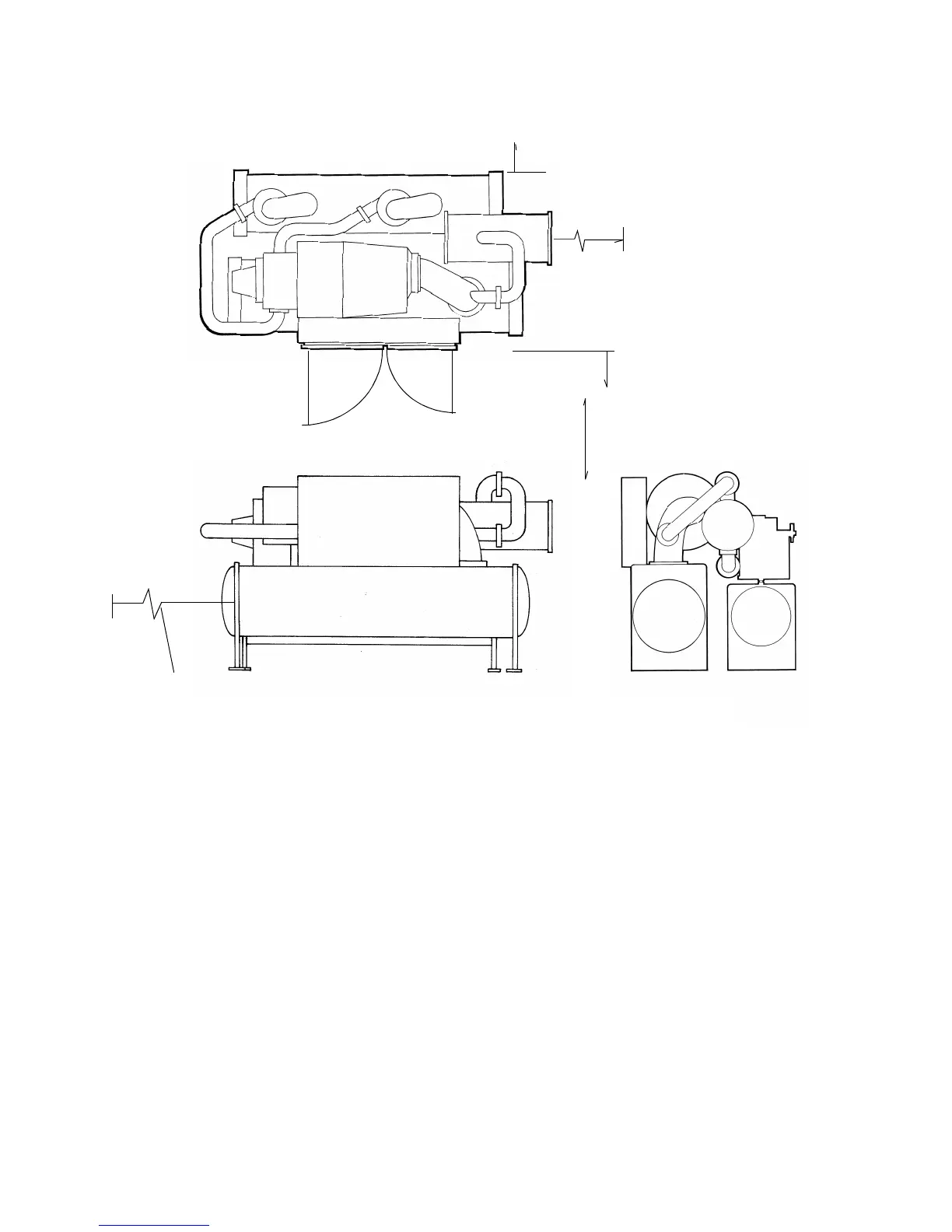
Figure 4
Recommended Operating and Service Clearances
NOTE: Maximum clearances are given. Depending on the unit configuration, some units may require less
clearance than others in the same category.
Ventilation
The unit produces heat even though the compressor
is cooled by the refrigerant. Make provisions to
remove heat generated by unit operation from the
equipment room. Ventilation must be adequate to
maintain an ambient temperature lower than 122
°
F
(50
°
C).
Vent the evaporator, condenser and compressor
pressure relief valves in accordance with all local and
national codes. Refer to “Pressure Relief Valves.”
Make provisions in the equipment room to keep the
chiller from being exposed to freezing temperatures
(32
°
F/0
°
C).
Water Drainage
Locate the unit near a large capacity drain for water
vessel drain-down during shutdown or repair.
Condensers and evaporators are provided with drain
connections. Refer to “Water Piping.” All local and
national codes apply.
Access Restrictions
Door clearances for the RTHC units are given in
Figure 4
. Refer to the unit submittals for specific “per
unit” dimensional information.
3’- 0” (914 mm)
Service
Clearance
3’- 0” (914 mm)
Service
Clearance
3’- 0” (914 mm)
Service
Clearance
Service Clearance
(Opp. Tube Removal)
Tube Removal
Clearance
(Either End)
DDE, CEF, CBC, BBB: 108” (2743 mm)
DFF, CDE, BCD: 126” (3200 mm)
DGG, CGG: 130” (3302 mm)
26.4” (671 mm) radius
35.6” radius
105
°
swing
3’- 0” (914 mm)