Installation, Operation and Maintenance 4 - 7
and condenser. If the differential is lower than
required, the unit will latch out and may start a “low
system differential restart inhibit timer,” if necessary,
to cool the rotors.
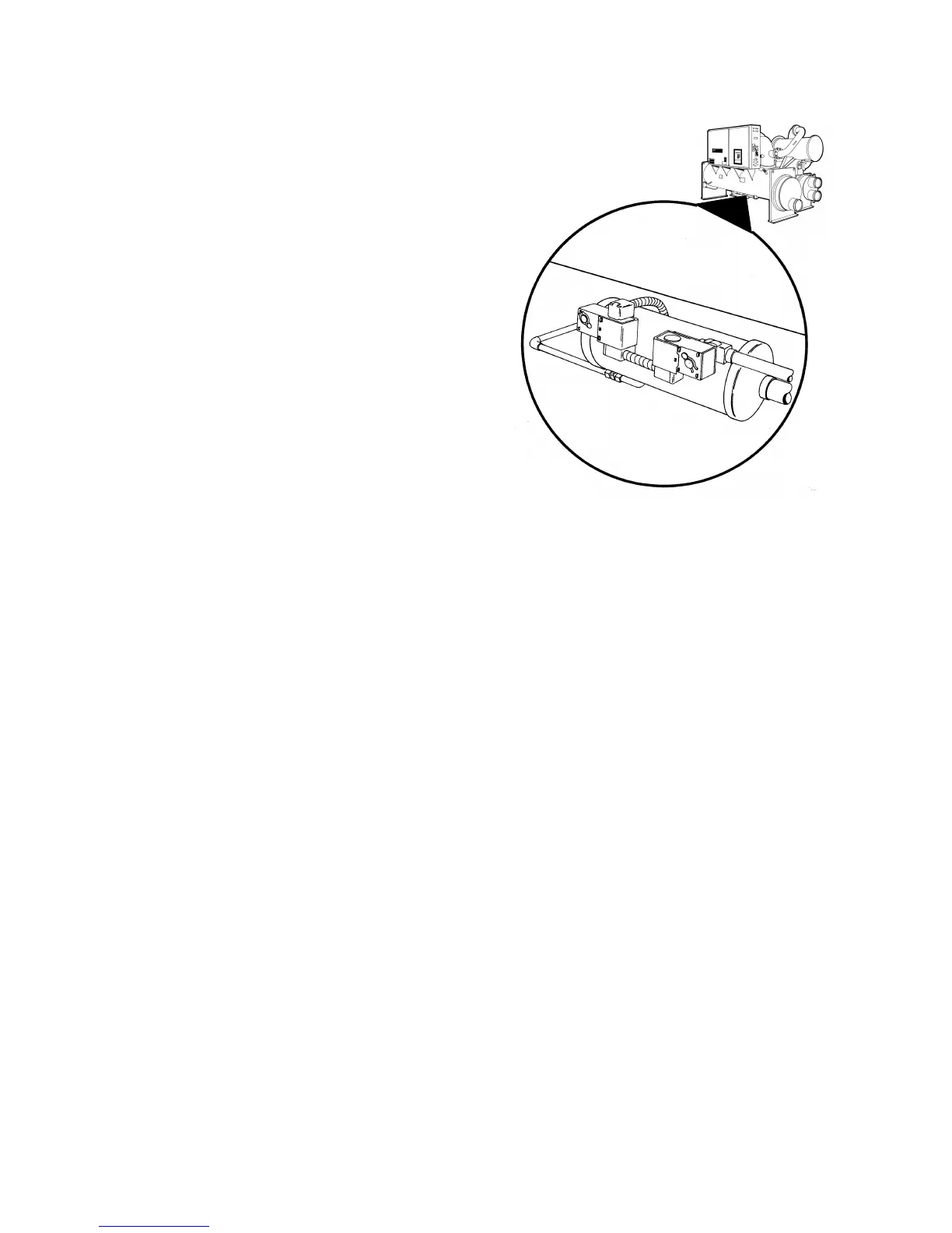
To ensure proper lubrication and minimize refrigerant
condensation in the oil sump, a heater is mounted on
the side of the oil sump. A signal from the UCP2
energizes this heater during the compressor off cycle
to maintain proper oil temperature. The heater
element is continuously energized while the
compressor is off and does not cycle on temperature.
Oil Filter
All Series R chillers are equipped with replaceable-
element oil filters. Each removes any impurities that
could foul the compressor internal oil supply
galleries. This also prevents excessive wear of
compressor rotor and bearing surfaces and promotes
long bearing life. Refer to the Section 9 for
recommended filter element replacement intervals.
Compressor Bearing Oil Supply
Oil is injected into the rotor housing where it is routed
to the bearing groups located in the motor and
bearing housing sections. Each bearing housing is
vented to compressor suction so oil leaving the
bearings returns through the compressor rotors to
the oil separator.
Compressor Rotor Oil Supply
Oil flowing through this circuit enters the bottom of
the compressor rotor housing. From there it is
injected along the rotors to seal clearance spaces
around the rotors and lubricate the contact line
between the male and female rotors.
Lubricant Recovery
Despite the high efficiency of the oil separators, a
small percentage of oil will get past them, move
through the condenser, and eventually end up in the
evaporator. This oil must be recovered and returned
to the oil sump. The function of active oil return is
accomplished by a pressure-actuated pump referred
to as the “gas pump.”
Gas Pump