Installation, Operation and Maintenance 2 - 25
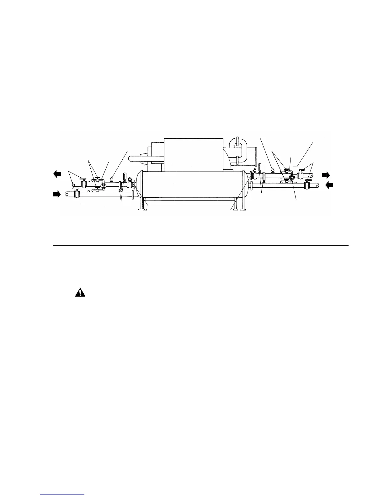
Water Pressure Gauges and
Thermometers
Install field-supplied thermometers and pressure
gauges (with manifolds, whenever practical) as
shown in
Figure 16
. Locate pressure gauges or taps
in a straight run of pipe; avoid placement near
elbows, etc. Be sure to install the gauges at the same
elevation on each shell if the shells have opposite-
end water connections.
To read manifolded water pressure gauges, open
one valve and close the other (depending upon the
reading desired). This eliminates errors resulting
from differently calibrated gauges installed at
unmatched elevations.
Figure 16
Typical Thermometer, Valving, and Manifold Pressure Gauge Set-up
Water Pressure Relief Valves
CAUTION
CAUTION: Install a pressure relief
valve in both evaporator and con-
denser water systems. Failure to do
so could result in shell damage.
Install a water pressure relief valve in one of the
condenser and one of the evaporator water box drain
connections or on the shell side of any shutoff valve.
Water vessels with close-coupled shutoff valves have
a high potential for hydrostatic pressure buildup on a
water temperature increase. Refer to applicable
codes for relief valve installation guidelines.
Flow Sensing Devices
Use field-provided flow switches or differential
pressure switches with pump interlocks to sense
system water flow. Flow switch locations are
schematically shown in
Figure 16
.
To provide chiller protection, install and wire flow
switches in series with the water pump interlocks, for
both chilled water and condenser water circuits (refer
to the Installation Electrical section). Specific
connections and schematic wiring diagrams are
shipped with the unit.
Flow switches must stop or prevent compressor
operation if either system water flow drops off below
the required minimum shown on the pressure drop
curves. Follow the manufacturer’s recommendations
for selection and installation procedures. General
guidelines for flow switch installation are outlined
below.
q Mount the switch upright, with a minimum of 5
pipe diameters straight, horizontal run on each
side.
q Do not install close to elbows, orifices or valves.
NOTE: The arrow on the switch must point in the
direction of the water flow.
q To prevent switch fluttering, remove all air from
the water system
Pressure Differential
Gauge
Pressure Differential
Gauge
Isolation
Valves
Isolation
Valves
Manifold
Manifold
Flow Switch
Flow Switch
Shutoff
Valves
Shutoff
Valves
Thermometers
Thermometers
Relief
Valve
Relief
Valve
Cond
Evap
Water
Flow
Water
Flow
Cond Water
Reg. Valve (Opt.)
NOTE: Refer to Trane Engineering Bulletin RLC-EB-3 for sound-sensitive applications.