2 - 6 RTHC-IOM-1C
Do not use the threaded holes in
the compressor to lift or assist in
lifting the unit. They are not
intended for that purpose and
could create a dangerous situa-
tion.
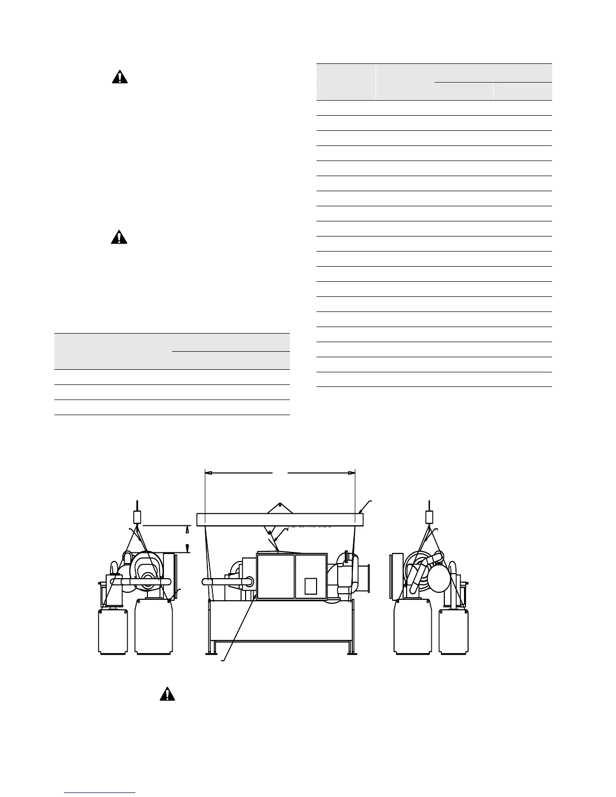
3 Install clevis connectors in lifting holes provided
on the unit. Attach lifting chains or cables to clevis
connectors as shown in
Figure 6
. Each cable
alone must be strong enough to lift the chiller.
CAUTION: Lifting Beam Location!
Always position the lifting beam so
that cables do not contact the unit.
Failure to do so may result in unit
damage.
Table 10
Weights and Rigging (Use with Figure 6 )
*
Designator corresponds to digits 6, 7, 12, 13, 16, 17 of model
number
Figure 6
Lifting the Unit
Unit Model
Number
*
Lifting
Weight (lb)
Dimension (ft) (Fig. 6)
A B
E3G3G3
20400 12 11
E3F2F3
17700 12 11
E3D2E2
15300 10 9
D3G3G3
20100 12 11
D3F2F3
17400 12 11
D3D2E2
15000 10 9
D2G3G3
20100 12 11
D2F2F3
17400 12 11
D2D2E2
15000 10 9
D1G2G2
19600 12 11
D1F1F2
16700 12 11
D1D1E1
15000 10 9
C2G1G1
18500 12 11
C2D3E3
14600 10 9
C2B3C2
13500 10 9
C1E1F1
15600 12 11
C1B3C2
13600 10 9
C1B2C1
13300 10 9
B2C2D2
10500 12 11
B2B2B2
9800 10 9
B1C1D1
10300 12 11
B1B1B1
9700 10 9
Unit Model
Number
*
Lifting
Weight (lb)
Dimension (ft) (Fig. 6)
A B
WARNING
To prevent personal injury or equipment damage, refer to Trane RTHC-SB-2
for units that must be disassembled due to limited access.
Lifting Cable
positioned
inside
discharge pipe -
No Contact
Attach
Eyebolt
to one
of three compressor
housing mounting holes
Note: Refer to specific unit
submittals or Figure 5 for
weight distribution
Evap
Cond
location
Unit Model Number
holes
Lifting
Starter
Controls
Cable
Anti-rolling
Anti-rolling
Cable
A Beam
Eyelet
Cable
Anti-rolling
B
24”