Installation, Operation and Maintenance 5 - 25
chiller with a solid state starter option, only the EA
series type starter applies. See section 3 for an
overview of the solid state starter and its settings.
Startup Contactor Test - Y-D Starters Only
This screen shall be displayed only when the starter
type is Y-Delta, otherwise this screen is skipped.
where disabled is the ROM default.
Rated Load Amps
This value should be set at the design rated load
amps as determined during the initial selection
process. If conditions change, contact Trane
Technical Support for new settings based on the new
operating conditions.
The range of values is 0-2500 in 1 amp increments.
The ROM default is 300 amps.
Motor Heating Constant
The range of values XXX is 0 to 100 minutes in 1
minute increments. The ROM default is 5 minutes.
This value is used in the calculation of the restart
inhibit timer. Refer to the following table for proper
settings based on compressor size.
Table 17
Recommended Motor Heating Constant Settings
Current Overload Setting #1
The range of values is decimal 00 through 31. The
ROM default is 00. Both the maximum acceleration
timers and the overload settings are not adjustable
from either the remote CLD or Tracer or any other
remote/external device.
The UCP2 will continuously monitor compressor
current to provide running overcurrent and locked
rotor protection. Overcurrent protection is based on
the phase with the highest current. It will trigger a
manually resettable diagnostic, shutting the unit
down, when the current exceeds a specified time-trip
curve.
The compressor overload is based on the unit RLA.
RLA is set in the UCP2 menu items along with the
current overload settings specific to a certain current
transformer (CT) and machine nameplate RLA. Use
the following procedure to set the current overload #1
and #2.
First determine the CT Factor where
CT Factor = Unit Nameplate RLA/ CT Rating x 100%
Look up the CT rating from the table below. The CT
Factor must be 66% or greater, but no more that
100% of the Nameplate RLA. Where more than one
selection is possible, use the CT rating that will give
the lowest CT Factor.
From the calculated CT Factor, the Motor Current
Overload Settings # 1 and #2 can be found in
Table
18
following. Note that when one setting is changed,
Level 2 Contactor Integrity Test: [d/e]
Press (+)(-) to Change Setting
Rated Load Amps: xxxx Amps
Press (+)(-) to Change Setting
Motor Heating Constant: xxx min
Press (+)(-) to Change Setting
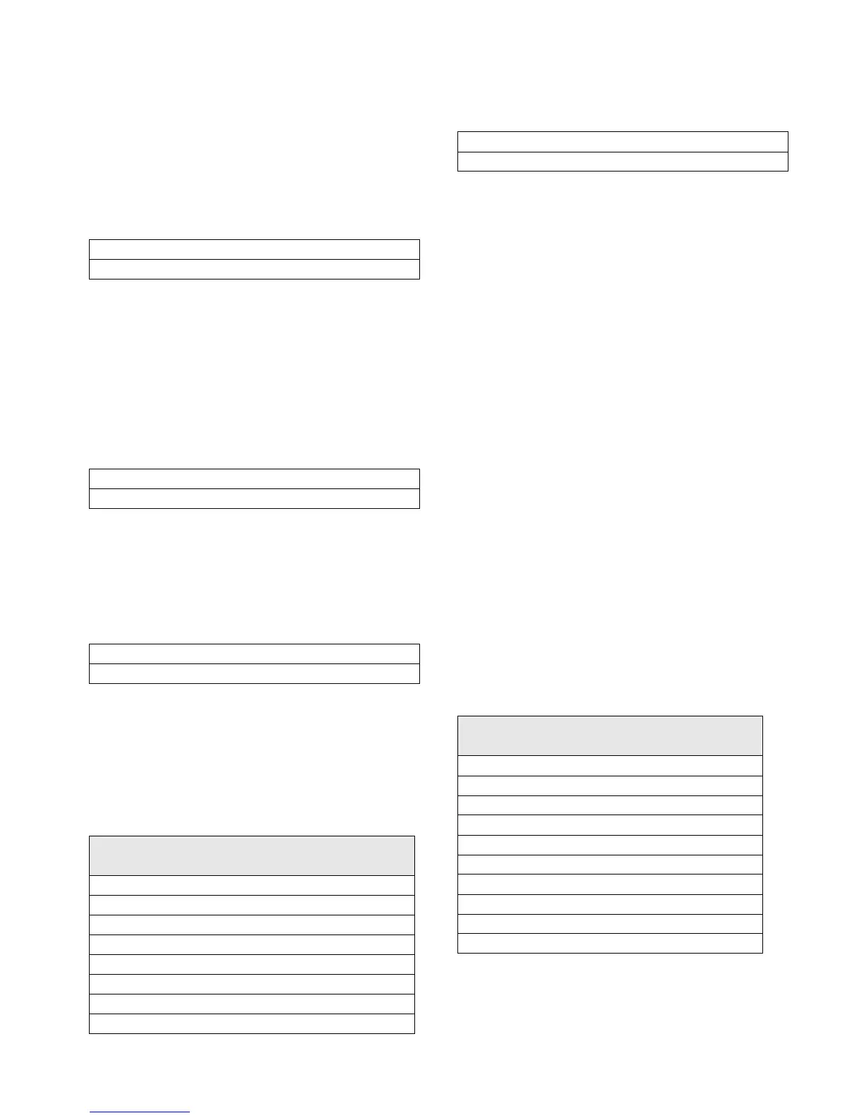
Compressor
Motor Heating Constant
(minutes)
B1 3
B2 3
C1 4
C2 4
D1 5
D2 5
D3 5
E3 5
Current Overload Setting #1: xxx
Press (+)(-) to Change Setting
Unit Nameplate
RLA
Extension
(X13580269-)
CT Rating Amp
33-50 -09 50
50-75 -10 75
67-100 -01 100
100-150 -02 150
134-200 -03 200
184-275 -04 275
267-400 -05 400
334-500 -06 500
467-700 -07 700
667-1000 -08 1000