Installation, Operation and Maintenance 5 - 7
The chiller operating modes display comes up first in
the standard report:
Line 1 (and 2 if needed) indicates a current condition
of the unit as shown in the following table
(Table 16)
.
In some cases, an associated timer or system
parameter will be displayed that assures the
transition to an expected mode is in progress,
particularly during the unit start-up sequence.
Ice Termination Setpoint/Source 3 4
Reset Chilled Water Setpoint/
Source
4
Evap Entering Water Temp 5 4
Condenser Entering Water Temp.
612
Condenser Leaving Water Temp
Current Limit Setpoint/Source 7 5
Active Current Limit Setpt/Setting
Source
8
Outdoor Air Temp 9
Time/Refrigerant Type 1
Refrigerant Monitor (option only) 6
Saturated Evap Refgt Temp
7
Compressor Discharge Temp
Compressor Starts/Running Time 8
Evap Refgt Pressure 9
Evap Approach Temp 10
Chilled Water Flow Switch Status 11
Saturated Cond Temp
13
Condenser Refrigerant Pressure
Condenser Approach Temp 14
Cond Water Flow Switch Status 15
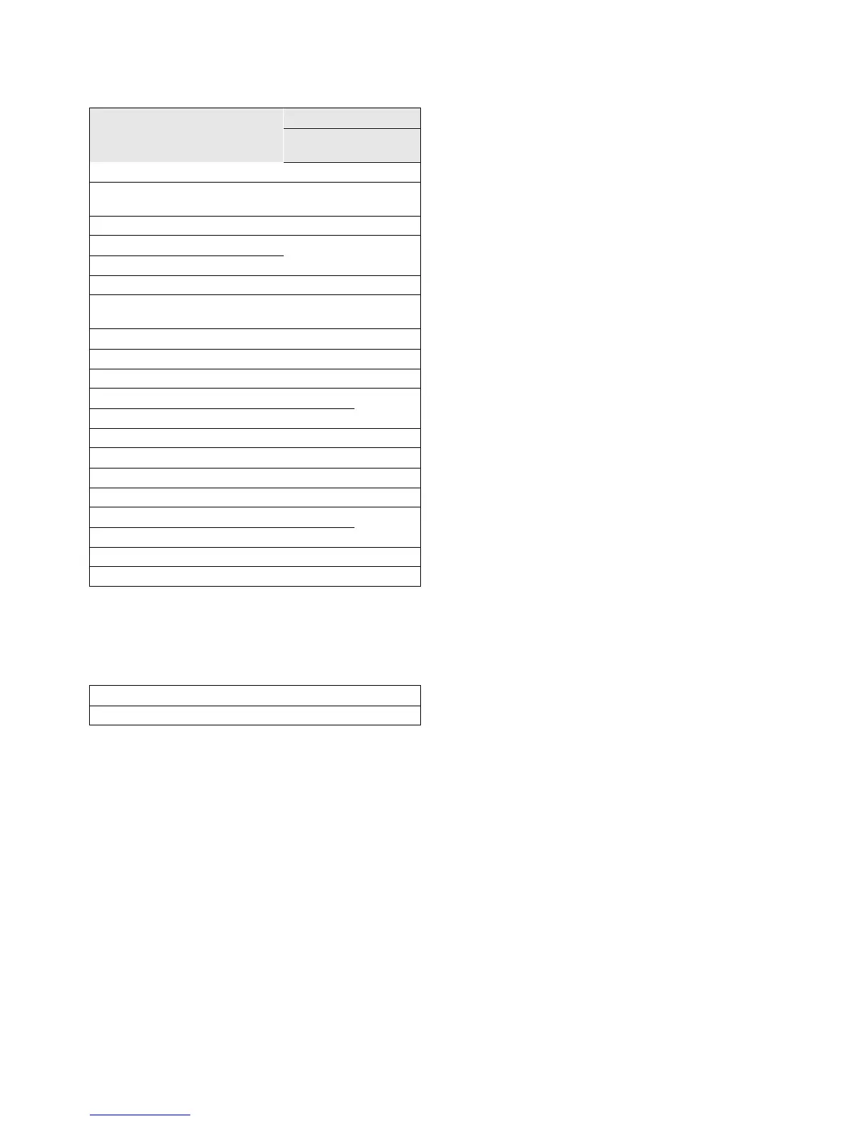
[Operating mode line 1]
[Operating mode line 2]
Table 15
Parameter Displayed
Sequence
Standard
Report
ASHRAE
Report