14 | IM-112 DECEMBER 2019
Vertical Turbine Pumps
2001299 - VTP- IOM
14 | IM-112 DECEMBER 2019
Vertical Turbine Pumps
2001299 - VTP- IOM
14 | IM-112 DECEMBER 2019
Vertical Turbine Pumps
2001299 - VTP- IOM
Vertical Turbine Pumps
Pre-installation
Document Name: 2001299-VTP-IOM-EN Page 14 of 67
Revision 3 Copyright © 2014, Weir Floway, Inc. All Rights Reserved. Issue Date: December 12, 2014
4.4.1 Lifting Pump Components and Pump Assemblies
Refer to the certified outline drawing for approximate pump assembly weights.
Pump components and assemblies must only be lifted from the appropriate locations. If there is any doubt
regarding proper lifting methods and locations, contact your nearest manufacturer’s representative.
• Cans/Barrels must be lifted using appropriate lifting devices attached to the mounting plate.
• Discharge heads are fitted with lifting lugs suitable to support the entire weight of the pump. Typically
two or more lifting lugs are supplied, a minimum two point lifting method is required (refer to Figure 4-2
on page 16 for fabricated heads and Figure 4-3 on page 16 for cast heads).
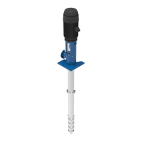
• Column and bowl assemblies must be lifted using an appropriate clamping fixture. The fixture must
positively lock to the item being lifted and have adequate strength to support the assembly’s weight. A
common fixture design employs beams and threaded rods that can be fastened around the assembly
(refer to Figure 4-4 on page 16). When clamping to threaded column, the upper column coupling must
be fully installed to provide a stop for the lifting clamp placed below the coupling. If the column is
supplied with optional lifting lugs, those may be used to lift the assembly.
Lift devices (straps, chains, etc.) attached to the pump must not exceed a 45 degree angle to the vertical
position. Exceeding this angle could overload the lifting location (refer to Figure 4-2 on page 16).
When lifting an assembled pump, it must be supported at minimally two locations. When lifting to the vertical
position, use the discharge head lifting lug locations to lift the pump assembly (refer to Figure 4-1 on page
15). For pump units over 40 ft in length, the pump shall be assembled during installation vertically in place
over the mounting location.
If the unit is supplied with a separate motor stand (that is, a component bolted between the driver and
discharge head), do not lift the entire pump unit from the motor stand. The motor stand lifting lugs are for
lifting the motor stand assembly only.
WARNING
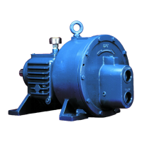
LIFTING DRIVERS AND AUXILIARY EQUIPMENT
Refer to the manufacturer’s instruction manual for proper lifting techniques of all drivers
and auxiliary equipment. Driver lifting locations must only be used to lift the driver. Do not
use the driver lifting locations to lift the assembled pump and driver.
WARNING
PERSONAL INJURY AND EQUIPMENT DAMAGE
Never lift any assemble by the bowl shaft or lineshaft. This can result in damage to the
shaft and personal injury.
WARNING
PERSONNEL INJURY
• Clamping fixtures that do not positively lock to the assembly being lifted may come loose
and cause personal injury. Always ensure the clamping fixture is of an appropriate design
to support the load and has secure means to lock onto the assembly being lifted.
• Do not lift bowl assemblies by placing lifting devices through the flange bolt holes, the
cast bowl flange holes may break through and result in dropping the load and personal
injury.