25 | IM-112 DECEMBER 2019
Vertical Turbine Pumps
2001299 - VTP- IOM
25 | IM-112 DECEMBER 2019
Vertical Turbine Pumps
2001299 - VTP- IOM
25 | IM-112 DECEMBER 2019
Vertical Turbine Pumps
2001299 - VTP- IOM
Vertical Turbine Pumps
Installation
Document Name: 2001299-VTP-IOM-EN Page 25 of 67
Revision 3 Copyright © 2014, Weir Floway, Inc. All Rights Reserved. Issue Date: December 12, 2014
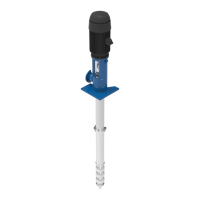
Figure 5-3: Motor Guide Bushing Location
5. Raise and center the driver over the pump.
6. Lower carefully until about 1/4
above mounting flange.
7. Rotate the driver until the junction box on the motor or the input shaft on the gear drive is in correct
position.
8. Align bolt holes and insert bolts.
9. Lower carefully into place ensuring that the driver and pump registers mate correctly.
10. Tighten the mounting bolts.
11. Refer to the driver manufacturer’s instruction manual for specific product requirements regarding
installation and start-up procedures.
12. Prior to installation of headshaft, check electric drivers for rotation. Establish electrical connections and
jog the motor briefly to check the rotation. Driver must rotate in counter clockwise direction when viewed
from the top end of the motor.
To change the direction of rotation on a three phase motor, interchange any two line leads.
13. Install the mechanical seal at this time, if the pump is so equipped and the mechanical seal was
shipped uninstalled. Refer to “Mechanical Seal” on page 33 for further details.
WARNING
PERSONNEL INJURY
Do not touch the rotating elements with hands to establish the direction of rotation. Visually
confirm the direction of rotation.
CAUTION
DAMAGE TO THE PUMP
Always check rotation before connecting the driver to the pump as reverse rotation while
the pump is connected can cause extensive damage to the pump.
Lower guide bushing located
inside holllow shaft at bottom