31 | IM-112 DECEMBER 2019
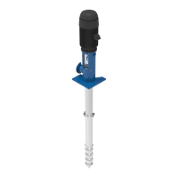
Vertical Turbine Pumps
2001299 - VTP- IOM
31 | IM-112 DECEMBER 2019
Vertical Turbine Pumps
2001299 - VTP- IOM
31 | IM-112 DECEMBER 2019
Vertical Turbine Pumps
2001299 - VTP- IOM
Vertical Turbine Pumps
Installation
Document Name: 2001299-VTP-IOM-EN Page 31 of 67
Revision 3 Copyright © 2014, Weir Floway, Inc. All Rights Reserved. Issue Date: December 12, 2014
• Use the highest discharge head that the unit is expected to operate against to calculate the impeller
adjustment value.
• For example: a pump designed to operate at 400 feet discharge head but will also be operated
against a closed valve for short intervals at which time it will produce 500 feet of pump pressure,
therefore 5 x 0.005
= 0.025. For a unit with 20 feet of column assembly, the calculation would be:
2 x 0.005 = 0.010". The initial adjustment would be 0.025
+ 0.010 + 0.015 = 0.050.
Refer to Table 5-1 to determine how many turns or fraction of a turn is necessary for the shaft diameter
supplied. For example: a 1 11/16 - 10
TPI shaft will provide 0.100 adjustment per turn of nut. Therefore
1/2 turn of the nut will provide the required 0.050
impeller setting in the previous example.
5.9 Impeller Adjustment - Hollow Shaft Driver
Impeller adjustment when using hollow shaft driver is accomplished at the top of the driver by the following
procedure.
1. Remove the driver canopy.
2. Install the headshaft as outlined in “Hollow Shaft Driver Installation” on page 24 if not already in place.
3. Install the driver clutch as per the driver instruction manual and bolt into place.
4. Install the gib key, ensuring the top of the gib key pushes down below the top of the clutch. To prevent
interference with the headshaft nut, fit the gib key to both the motor clutch and the headshaft. The key
must slide in smoothly in the keyway.
5. Check the shaft position; the impellers must be fully seated against the bowls prior to adjusting the
impellers.
6. Thread the headshaft nut down (right hand threads) until the impellers are lifted off their seat and the
shaft rotates freely. When semi-open impellers are used, the correct determination of the point where
the impellers just barely clear their seat is very important for proper adjustment.
7. Adjust the impellers as outlined in “Impeller Adjustment - General” on page 29.
8. Lock the headshaft nut with the lockscrew inserted down through the holes in the headshaft nut and
threaded into the driver clutch.
Shaft Diameter Headshaft Nut (thread/inch) Inches per Full Turn of Adjusting Nut
3/4
16 TPI - R.H. 0.063
1
14 TPI - R.H. 0.071
1 1/4
12 TPI - R.H. 0.083
1 1/2
12 TPI - R.H. 0.083
1 11/16
10 TPI - R.H. 0.100
1 15/16
12 TPI - R.H. 0.083
2 1/4
12 TPI - R.H. 0.083
2 7/16
12 TPI - R.H. 0.083
2 11/16
12 TPI - R.H. 0.083
2 15/16
10 TPI - R.H. 0.100
3 3/16
8 TPI - R.H. 0.125
3 7/16
8 TPI - R.H. 0.125
Table 5-1: Shaft Diameter Turns
CAUTION
DAMAGE TO THE PUMP AND THE DRIVER
Always ensure the headshaft nut is locked before starting the driver to avoid damage to the
pump and the driver.