28 | IM-112 DECEMBER 2019
Vertical Turbine Pumps
2001299 - VTP- IOM
28 | IM-112 DECEMBER 2019
Vertical Turbine Pumps
2001299 - VTP- IOM
Vertical Turbine Pumps
Installation
Document Name: 2001299-VTP-IOM-EN Page 28 of 67
Revision 3 Copyright © 2014, Weir Floway, Inc. All Rights Reserved. Issue Date: December 12, 2014
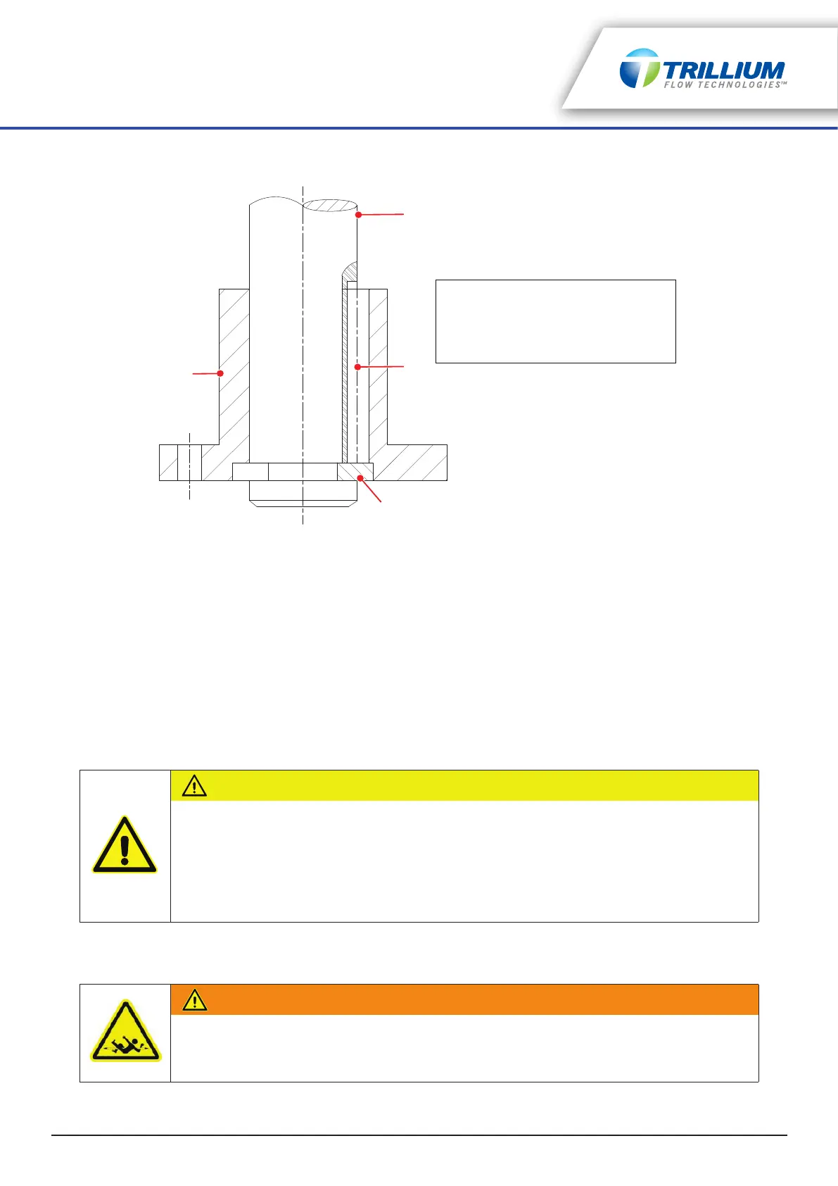
Figure 5-5: Driver Half Coupling Correctly Positioned
5. Install the mechanical seal at this time if the pump is so equipped and the mechanical seal was shipped
uninstalled. Refer to “Mechanical Seal” on page 33 for further details.
6. Install the pump half coupling onto the headshaft:
a. Slide the pump half coupling onto the shaft.
b. Install the key and push down to clear the threads.
c. Thread the adjusting nut (right hand threads) onto the shaft until the end of the shaft is even with the
top of the adjusting nut.
7. Center the motor over the pump and rotate to align the mounting holes and properly align the power
conduit box. For gear drives, rotate the input shaft into desired position.
8. Lower the driver carefully into place ensuring that the driver and pump registers mate correctly. Check
the shaft gap between the motor and pump shaft against the schematic provided.
9. Bolt the driver to the discharge head.
10. Refer to the driver manufacturer’s instruction manual for specific product requirements regarding
installation and start-up procedures.
CAUTION
EQUIPMENT DAMAGE
• If the discharge head or motor stand was supplied with jacking screws, the driver must be
manually aligned to the pump shaft prior to bolting it down. Failure to align the driver may
result in equipment damage. The driver shaft must be aligned to within 0.002" max. TIR
with respect to the precision machined ID on the pump's driver mounting plate.
• If jacking screws are not supplied, manual driver alignment is not required.
WARNING
PERSONNEL INJURY
Do not touch the rotating elements with hands to establish the direction of rotation. Visually
confirm the direction of rotation.
1
2
3
4
1. Driver Shaft
2. Square Key
3. Split Circular Thrust Ring
4. Driver Half Coupling (fits over split
circular thrust ring and holds in place)