Vertical Turbine Pumps
Installation
Document Name: 2001299-VTP-IOM-EN Page 26 of 67
Revision 3 Copyright © 2014, Weir Floway, Inc. All Rights Reserved. Issue Date: December 12, 2014
14. Clean all the shaft threads (on top shaft and both ends of headshaft). Try the lineshaft coupling and
headshaft nut on their respective threads. These must thread on by hand. If not, clean up the threads
with a fine three cornered file. Check the ends of the shaft where they butt inside the lineshaft coupling.
Ends must be square and clean. Fit the gib key to both motor clutch and headshaft. The key must slide
smoothly in both keyways.
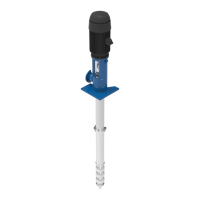
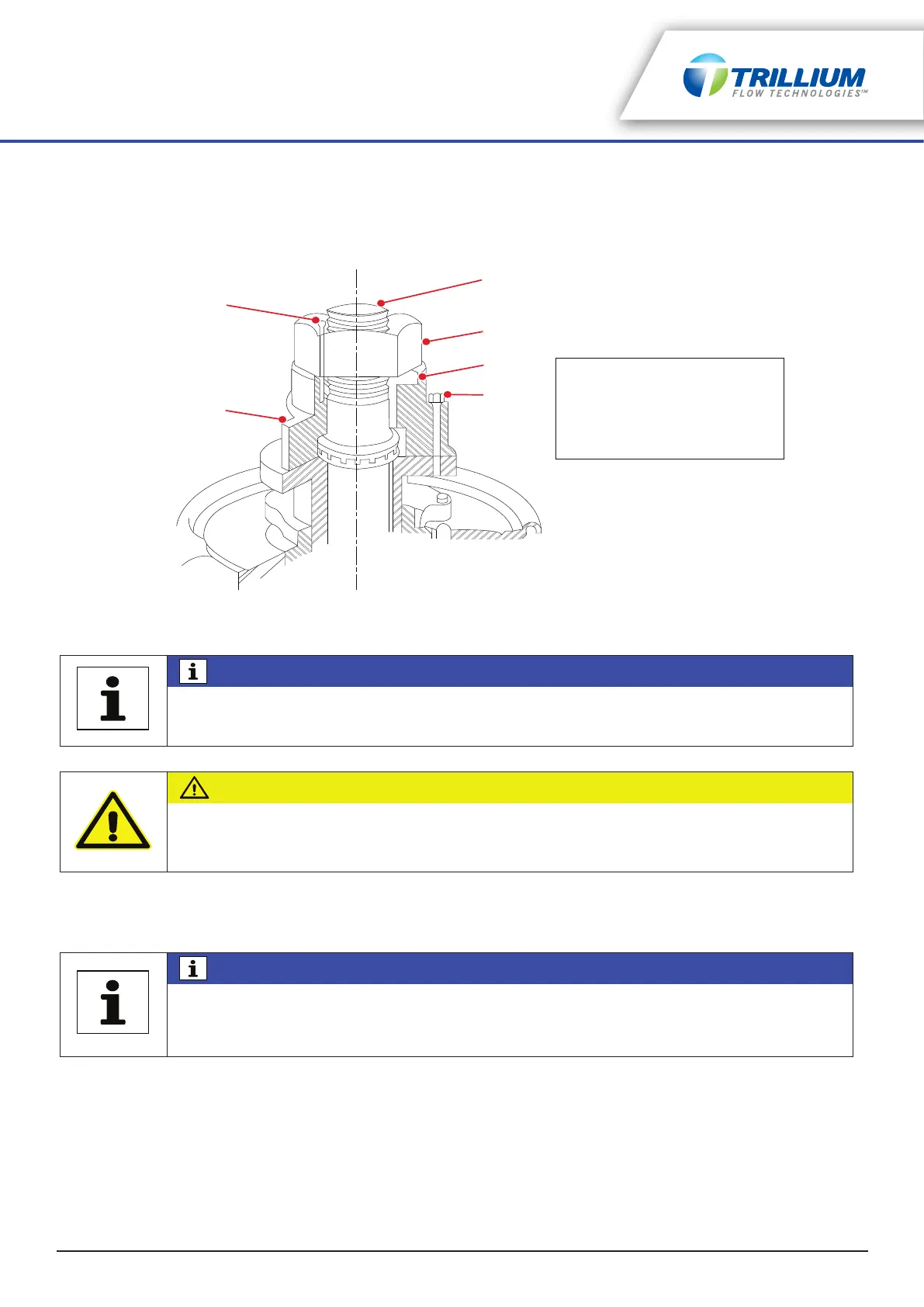
Figure 5-4: Hollow Shaft Driver Clutch
15. Lubricate the top shaft threads and thread (left hand threads) the lineshaft coupling half way onto the top
shaft.
16. Lubricate the headshaft threads and lower the headshaft carefully down through the driver, and thread
into the lineshaft coupling. Shafts must butt against each other.
17. Install the clutch on the driver and ensure that it fits down properly.
18. Install pre-fitted gib key in the clutch and the shaft.
19. Thread adjusting the nut down (right hand threads) on the shaft until it bears against the clutch.
20. Refer to “Impeller Adjustment - General” on page 29 for impeller adjustment.
21. Adjust mechanical seal after adjusting impellers.
NOTICE
For units equipped with one piece headshaft (no lineshaft coupling between driver and
pump) steps 15 and 16 will not be applicable.
CAUTION
EQUIPMENT DAMAGE
Apply thread lubricant only to male shaft threads sparingly to avoid buildup between ends
of shaft which can cause misalignment.
NOTICE
Headshaft must stand centered (long shafts may lean slightly from own weight; however,
they can be centered without effort) in the driver hollow shaft. If not, check the driver
mounting flange for improper mounting and re-clean the shaft ends coupled inside the
discharge head.