32 | IM-112 DECEMBER 2019
Vertical Turbine Pumps
2001299 - VTP- IOM
32 | IM-112 DECEMBER 2019
Vertical Turbine Pumps
2001299 - VTP- IOM
32 | IM-112 DECEMBER 2019
Vertical Turbine Pumps
2001299 - VTP- IOM
Vertical Turbine Pumps
Installation
Document Name: 2001299-VTP-IOM-EN Page 32 of 67
Revision 3 Copyright © 2014, Weir Floway, Inc. All Rights Reserved. Issue Date: December 12, 2014
5.10 Impeller Adjustment - Solid Shaft Driver (thrust bearing in driver)
Impeller adjustment when using a solid shaft driver (with thrust bearing in driver) is accomplished with the
adjustable flanged coupling located below the driver.
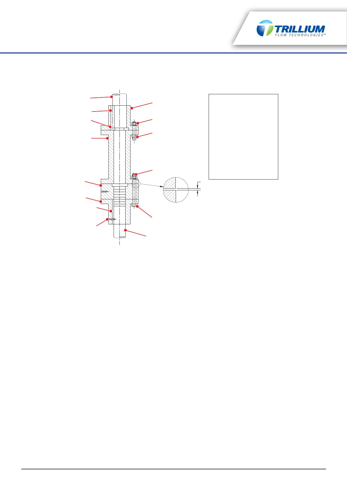
Figure 5-7: Adjustable Flanged Coupling for Solid Shaft Drivers
(illustrated with spacer)
5.10.1 Adjustable Flanged Couplings
1. Assemble the coupling on the pump and the driver as outlined in “Solid Shaft Driver Installation” on
page 27.
2. Back off the adjusting nut up the shaft (threads are right hand) until the nut bears firmly against the
spacer or driver shaft and the headshaft does not move down. This ensures that the impellers are all the
way down against their seat and in proper position for starting the adjustment.
3. Thread the adjusting nut down until proper impeller adjustment as outlined in “Impeller Adjustment -
General” on page 29 can be measured between the adjusting nut and spacer or driver half coupling as
shown in Figure 5-7 on page 32.
4. Slide the pump half coupling up the shaft and align the adjusting nut bolt holes with those in the pump
half coupling. Rotate the driver shaft until bolts can be inserted and tightened.
5. Tighten all the bolts. This will raise the impellers to correct operating position.
5.11 Impeller Adjustment - Solid Shaft Driver (thrust bearing in pump)
Impeller adjustment when using a solid shaft driver (with thrust bearing in pump) is accomplished using the
adjusting nut located on top of the pump’s thrust bearing.
1. Install the thrust bearing drive key, ensuring the top of the key pushes down below the top of the thrust
bearing clutch. To prevent interference with the adjusting nut, fit the key to both the clutch and the top
lineshaft. The key must slide in smoothly in the keyway.
2. Check the shaft position; the impellers must be fully seated against the bowls prior to adjusting the
impellers.
3. Thread the adjusting nut down (right hand threads) until the impellers are lifted off their seat and the
shaft rotates freely. When semi-open impellers are used, the correct determination of the point where
the impellers just barely clear their seat is very important for proper adjustment.
4. Adjust the impellers as outlined in “Impeller Adjustment - General” on page 29.
1
2
3
3
4
5
6
7
8
9
10
11
12
13
1. Driver Half Coupling
2. Spacer Bolts
3. Lock Nuts
4. Coupling Bolts
5. Headshaft
6. Dowel Pin
7. Pump Key
8. Pump Half Coupling
9. Adjusting Nut
10. Spacer (optional)
11. Split Circular Thrust Ring
12. Driver Key
13. Driver Shaft
Measure impeller adjustment
here before tightening
coupling bolts