18 | IM-112 DECEMBER 2019
Vertical Turbine Pumps
2001299 - VTP- IOM
18 | IM-112 DECEMBER 2019
Vertical Turbine Pumps
2001299 - VTP- IOM
18 | IM-112 DECEMBER 2019
Vertical Turbine Pumps
2001299 - VTP- IOM
Vertical Turbine Pumps
Pre-installation
Document Name: 2001299-VTP-IOM-EN Page 18 of 67
Revision 3 Copyright © 2014, Weir Floway, Inc. All Rights Reserved. Issue Date: December 12, 2014
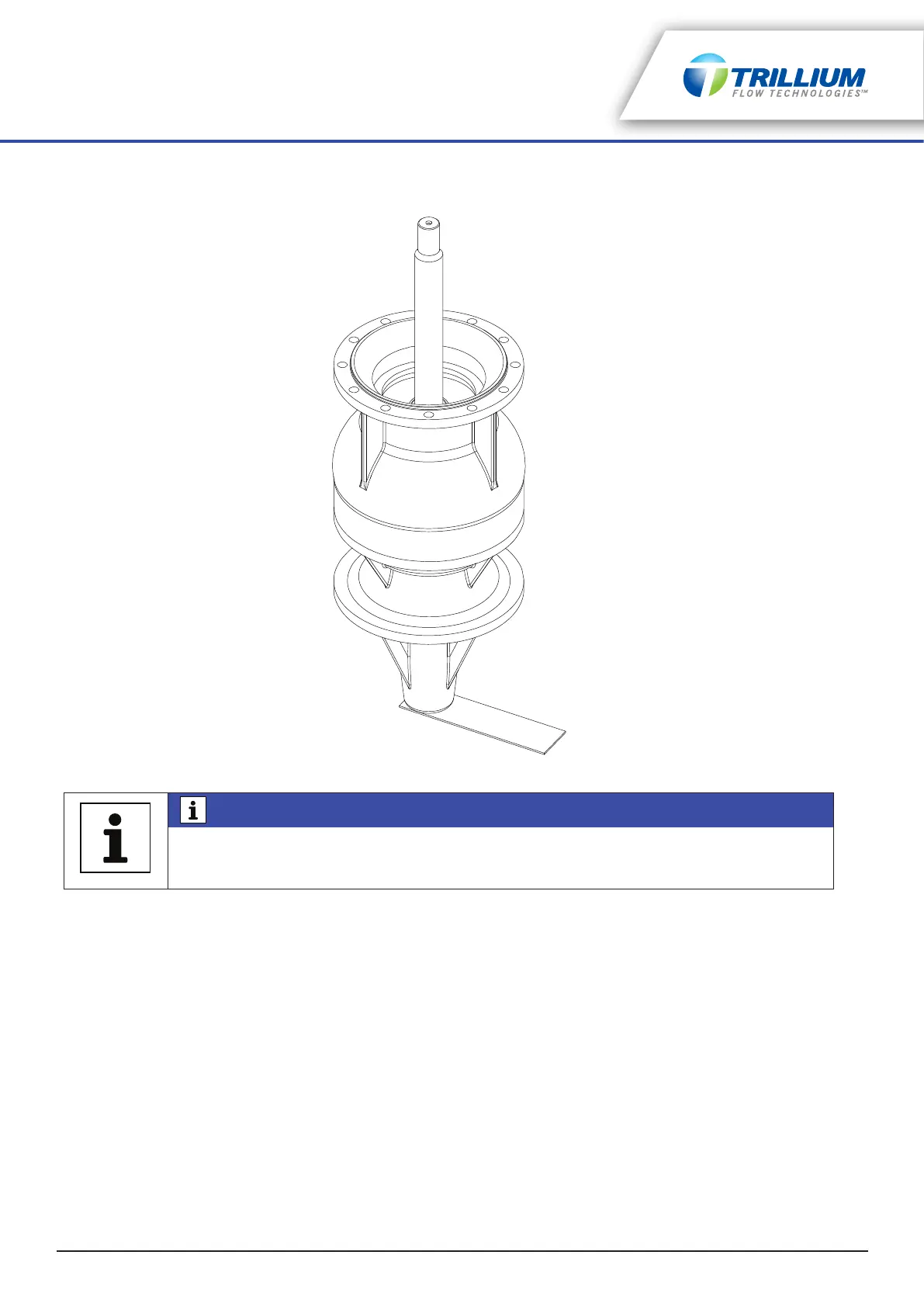
Figure 4-5: Shaft Locking Plate
6. Check the proposed minimum liquid level in the sump against the pump length; the bottom stage of the
pump must be submerged at all times and satisfy the minimum required submergence and NPSHR.
7. Clean the sump and piping system before installing the pump.
8. Check the installation equipment to ensure it can safely handle the equipment.
9. Check the pump connections (bolts, nuts, etc.) for tightness. These are properly tightened before
leaving the factory. However, some connections can become loose during transit.
10. For hollow shaft drivers, check the clutch size against the shaft size that must pass through the clutch.
Sometimes the shaft size coming through the discharge head is different from the shaft size going
through the driver (ensure the clutch is checked against to correct shaft).
11. For solid shaft drivers, check the motor shaft size against the driver half coupling bore size. Also check
all keys.
NOTICE
Shaft type seals are shipped separately and are not installed in the seal housing. A tag is
supplied indicating that the seal is not installed. Lock down plate is not supplied for units
which have no seals installed.