41 | IM-112 DECEMBER 2019
Vertical Turbine Pumps
2001299 - VTP- IOM
41 | IM-112 DECEMBER 2019
Vertical Turbine Pumps
2001299 - VTP- IOM
41 | IM-112 DECEMBER 2019
Vertical Turbine Pumps
2001299 - VTP- IOM
Vertical Turbine Pumps
Maintenance
Document Name: 2001299-VTP-IOM-EN Page 41 of 67
Revision 3 Copyright © 2014, Weir Floway, Inc. All Rights Reserved. Issue Date: December 12, 2014
• Replace the gland, tighten the nuts and make sure the gland enters the box squarely. Keep the packing
under moderate pressure for one minute to allow it to cold flow and adjust itself. Back off on the gland
until loose and the gland nuts are hand tight before starting the pump.
7.3 Start-up with New Packing
• Check that the bypass line (if used) is connected and packing gland is loose.
• Start the pump and allow it to run for 20 to 30 minutes; do not tighten the gland during this “run-in” period
even if leakage is excessive. If the leakage continues to be more than normal, adjust as outlined in
“Packing Box Adjustment” on page 36.
• If the new packing causes excess heating during run-in, flush the shaft and packing box area with cold
water or shut the pump down. Allow to cool if necessary.
7.4 Auxiliary Packing Box Maintenance
• Pumps equipped with mechanical seals may also be provided with an auxiliary packing box to restrict
leakage, should the mechanical seal fail.
• This packing gland must be left loose since under regular operation the packing is not cooled or
lubricated by the pumpage.
• This packing box arrangement is designed to help contain leakage past the mechanical seal in the event
of a seal failure. It is not designed as a primary seal and must not be used as such.
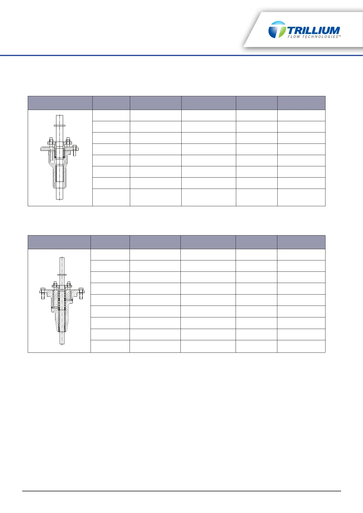
Shaft Size # Packing Rings Packing Ring Size Depth of Box O.D. of Packing
3/4 5 5/16 1 23/32 1 3/8
1 5 5/16 1 23/32 1 5/8
1 3/16, 1 1/4 5 3/8 2 1/16 2
1 1/2 5 3/8 2 1/16 2 1/4
1 11/16 5 7/16 2 13/16 2 5/8
1 15/16 6 3/8 2 13/32 2 3/4
2 1/4 6 3/8 2 3/4 3 1/16
2 7/16 6 3/8 4 3/4 3 1/4
Table 7-1: Standard Type Box
Shaft Size # Packing Rings Packing Ring Size Depth of Box O.D. of Packing
3/4 6 5/16 3 5/8 1 3/8
1 6 5/16 3 5/8 1 5/8
1 3/16, 1 1/4 7 3/8 4 5/8 2
1 1/2 7 3/8 4 5/8 2 1/4
1 11/16 7 7/16 4 7/8 2 5/8
1 15/16 8 3/8 4 7/8 2 11/16
2 1/4 6 1/2 4 3/4 3 1/4
2 7/16 6 1/2 4 3/4 3 1/2
2 11/16 7 1/2 4 1/2 3 3/4
Table 7-2: Hi-pressure Type Box