47 | IM-112 DECEMBER 2019
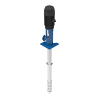
Vertical Turbine Pumps
2001299 - VTP- IOM
47 | IM-112 DECEMBER 2019
Vertical Turbine Pumps
2001299 - VTP- IOM
47 | IM-112 DECEMBER 2019
Vertical Turbine Pumps
2001299 - VTP- IOM
Vertical Turbine Pumps
Repairs
Document Name: 2001299-VTP-IOM-EN Page 47 of 67
Revision 3 Copyright © 2014, Weir Floway, Inc. All Rights Reserved. Issue Date: December 12, 2014
b. Solid Shaft Driver: Unbolt the driver coupling to lower the pump shaft. Remove coupling components
(driver half coupling may be left in place, ensure it is safely secured to the driver shaft).
4. Remove the bolts which attach the driver to the discharge head.
5. Lift the driver off the pump and set it on wooden supports. For solid shaft drivers ensure the supports are
high enough to clear the shaft and coupling half, which project beneath the motor mounting plate.
6. Disconnect the discharge (and suction, if applicable) piping from the pump.
7. Remove the anchor bolt nuts, or bolts from the mounting flange.
8. Lift the pump vertically until the pump suction clears the foundation, or the mounting flange. Remove the
mounting flange gasket if required.
9. Cover the opening in the foundation.
10. Lower the pump and position horizontally on a stable support in a suitable area for disassembly.
11. For packing box, mechanical seal and enclosed lineshaft construction do the following:
a. Packing Box Construction: remove the slinger and the packing gland.
b. Mechanical Seal Construction: loosen seal cover fasteners and remove the seal housing cover.
c. Enclosed Lineshaft Construction: remove the lockscrew and lubrication line and unscrew the tension
nut assembly. Threads are left hand.
12. Remove the fasteners which attach the packing box, tension plate or seal housing to the discharge
head.
13. Remove the packing box, tension plate or seal housing.
14. Disconnect the bowl assembly or top column from the discharge head. This connection may be flanged
or threaded. If threaded, the thread will be right hand.
15. Remove the discharge head being careful not to damage the shaft.
16. Disconnect the column pipe (if present) at first joint below the top and remove from the shaft.
For any major repairs it is recommended to take the unit to a shop or any other clean area
which has smooth flooring and overhead lifting equipment.
For sleeve mounted mechanical seals, remove the seal and sleeve assembly along with
the cover.
Refer to the manufacturer's instruction manual for further mechanical seal details.
If type FF-2 or FF-9 mechanical seal is used, loosen the set screws which lock the seal
assembly to the shaft before removing the seal housing.
Before proceeding further, make sure the discharge head and the bowl/column assembly
are supported independently of each other.