Do you have a question about the TSI Instruments Certifier Plus and is the answer not in the manual?
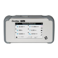
Overview of the portable, multi-functional pneumatic tester for medical use.
Lists all parts included in the Standard Kit (Model 4080-S).
Lists all parts included in the Full Kit (Model 4080-F).
Details on optional accessory kits for the Certifier™ Plus system.
Lists additional accessories available for purchase separately.
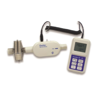
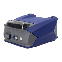
Overview of the Certifier™ Plus system components and their functions.
Details on connecting modules, power, and basic operation of the analyzer.
Explains the touchscreen interface, parameter screens, and graph screens.
How to acquire, export, and manage data and configurations.
Lists and defines available measurement parameters and their units.
Powering on, warming up, connecting modules, filters, and sensors.
Setting breath triggers and connecting the high flow module to a ventilator.
Performing flow measurement checks, zeroing sensors, and calibration.
Explanation of the main Parameter and Graph screens and their elements.
Using module cards, menu screens, and device information for navigation.
Setting up measurements, units, gas types, triggers, and configurations.
Editing graph displays, scaling axes, and setting trigger timing.
Procedures for zeroing pressure sensors and calibrating the oxygen sensor.
Capturing snapshots, continuous logs, waveform logs, and exporting data.
Managing, previewing, deleting, and viewing saved data files.
Adjusting general settings, date/time, display, and updating firmware.
Lists common symptoms, causes, and corrective actions for system problems.
Instructions for recharging and replacing the internal battery.
Procedures for cleaning modules and replacing the oxygen sensor.
Information on factory calibration recommendations and return procedures.
Details on dimensions, flow connectors, and weight of system components.
Operating conditions, temperature, humidity, and battery/adapter specifications.
Information on regulatory compliance marks and FCC statements.
Detailed specifications for flows, volumes, pressures, and other measurements.
Details on CSV file structure for parameter and graph screen snapshots.
Structure of CSV files for continuous and waveform data logging.
| Brand | TSI Instruments |
|---|---|
| Model | Certifier Plus |
| Category | Test Equipment |
| Language | English |