Flow Analyzer Setup 3-3
Start and end of the breath can also be triggered by a TTL voltage signal given at the connector on the
Trigger Input
Flow Module. The connector is a 3.5 mm mono audio jack plug.
If multiple flow modules are connected to the interface module (ex. 4081 and 4082), the 4081 high
flow will always control triggers for the instrument. If both connected flow modules are the same model
(ex. two 4081s or two 4082s), then the flow module connected to the A port will control triggering.
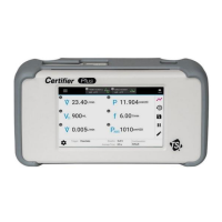
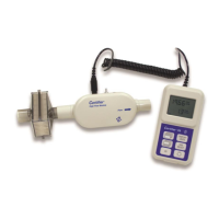
C o n n e c t t h e Ce r t i f ie r P l u s H i g h F l o w Mo d u l e
t o a V e n t i l a t o r
Follow the steps below to connect the Plus 4081 High Flow Module to a bi-directional test
circuit such as a mechanical ventilator:
1. Connect the high flow module to the interface module using a coiled cable connector. To remove
the coiled cable from the flow module, pull its locking connector shell (not the cable) from the
flow module.
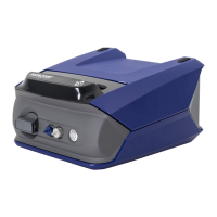
2. Connect an inlet filter to the upstream end of the Plus High Flow Module.
3. Connect the AC adapter to the DC power input of the Certifier Plus Interface Module. The battery
will charge in the instrument when the AC adapter is plugged in. The instrument can also be
operated on battery power without a wired power connection.
4. Press the power button to turn on the Certifier Plus Flow Analyzer. After bootup has completed,
wait 1 minute for the pressure transducers and flow sensor to warm up.
5. Perform pre-test checks including zeroing the 4081 pressure transducers and calibrating the
oxygen sensor (if applicable). Refer to the Pre-Test Checks section for detailed instructions.
6. Install the flow module into the test circuit between a Y-fitting and a test lung. Align the flow
direction arrow on the flow module with the positive direction of flow through the circuit. For
To Patient
on the ventilator.
instructions on where to connect the Certifier Plus Flow Module.
7. Connect the low pressure measurement and oxygen sensor (if applicable) to the flow module.
Refer to the Instrument Setup section for low pressure and oxygen sensor setup instructions.
8. Configure the Certifier Plus Flow Analyzer settings from the interface display as desired for the
instrument under test. If available, a saved configuration specific to the model under test can be
loaded at this time. The manufacturer of the device under test will specify the settings and
measurement parameters in which to test.