Flow Analyzer Overview 2-3
O p e r a t i o n O v e r v i e w
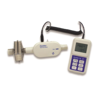
Flow Modules
You can connect or disconnect Flow Modules from the Interface Module at any
time during normal operation without having to reboot the instrument or change settings. Flow
modules can be connected to either of the flow module ports (A or B) on the interface module. Two
flow modules can be connected and operated through the interface module at the same time, by
connecting two of the same Flow Modules (ex. 4081 and 4081) or two different Flow Modules
(ex. 4081 and 4082).
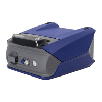
End Caps
TSI
®
Flow Analyzers measure flow utilizing an exposed thermal flow sensor that is highly sensitive to
foreign matter and particles within the gas flow. TSI
®
supplies end caps for both the high flow module
and low flow module and recommends that flow module ends be capped when not in use.
To avoid damage to the Plus Test System components, always cap the ends
of the Flow Modules when not in use.
Lithium Ion Batteries
The model 4089 Certifier Plus Interface Module utilizes a 4-cell lithium ion battery pack which can
provide up to 8 hours of continuous operation from a full charge. The battery pack is calibrated and
installed into the 4089 Interface Module at the factory. The battery pack is rechargeable and can be
charged internally by providing power to the Certifier Interface Module via the AC power adapter. The
Certifier Plus batteries cannot be charged externally from the instrument.
Supplying Power
The Certifier Plus Interface Module provides power to any Certifier Plus Flow Modules when
connected via the coiled cable connector. The interface module can be powered by internal Lithium-
Ion batteries or an AC power adapter can be used. Refer to Chapter 7 of this manual for the Certifier
Plus power supply specifications.
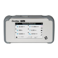
If the AC adapter is delivering power to the Certifier Interface Module with the battery is installed, the
battery symbol on the display will contain a lightning bolt to indicate that the battery is being charged. If
the AC adapter is powering the instrument but no battery is installed, a question mark symbol will
appear within the battery symbol.
When running the Certifier Plus test system on battery power without an AC connection, the
device will shut down automatically if the battery charge reaches 5% in order to prevent battery
damage from occurring.
Power Button LED States
The power button contains an LED that changes state and color depending on the condition of the
Certifier Plus instrument. If the Certifier Plus test system is running with the battery installed while
connected to power via the power cable, then the power button will display the following LED states:
• Blinking red: 010% battery charge
• Solid red: 1020% battery charge
• Solid green: > 20% battery charge