v
Contents
Warranty ............................................................................................................................................................ iii
Contents ............................................................................................................................................................. v
CHAPTER 1 Introduction and Parts Identification ................................................................................... 1-1
Introduction ........................................................................................................................................... 1-1
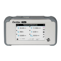
Interface Module ................................................................................................................................ 1-1
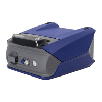
High Flow Module .............................................................................................................................. 1-1
Low Flow Module ............................................................................................................................... 1-1
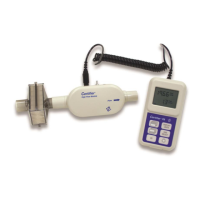
Oxygen Sensor .................................................................................................................................. 1-1
List of Standard Components ............................................................................................................... 1-2
Certifier Plus High Flow Test System, Standard Kit (Model 4080-S)............................................. 1-2
Certifier Plus High Flow Test System, Full Kit (Model 4080-F) ...................................................... 1-3
List of Accessory Kits ............................................................................................................................ 1-4
Certifier Plus Low Flow Module Kit (Model 4082) .......................................................................... 1-4
Certifier Oxygen Sensor Kit (Model 4073) ..................................................................................... 1-4
Mounting Kit, for Certifier Plus Interface Module (PN 130398) ...................................................... 1-4
Mounting Kit, for Certifier Plus Interface and Flow Module (PN 130399) ...................................... 1-5
Certifier Connector Kit (PN 130391) .............................................................................................. 1-5
Flow Resistor Kit (PN 130395) .......................................................................................................... 1-5
Other Optional Accessories .................................................................................................................. 1-6
CHAPTER 2 Flow Analyzer Overview ........................................................................................................ 2-1
Instrument Overview ............................................................................................................................. 2-1
4089 Interface Module, Back ............................................................................................................. 2-1
4089 Interface Module, Front ............................................................................................................. 2-1
4081 High Flow Module, Back ........................................................................................................... 2-2
4081 High Flow Module, Front ........................................................................................................... 2-2
4082 Low Flow Module ...................................................................................................................... 2-2
Operation Overview .............................................................................................................................. 2-3
Flow Modules ..................................................................................................................................... 2-3
End Caps ........................................................................................................................................... 2-3
Lithium Ion Batteries .......................................................................................................................... 2-3
Supplying Power ................................................................................................................................ 2-3
Power Button LED States .................................................................................................................. 2-3
Touchscreen Display ......................................................................................................................... 2-4
User Configurations ........................................................................................................................... 2-4
Data Acquisition and Export .............................................................................................................. 2-4
USB Communications ........................................................................................................................ 2-4
Measurements and Units ...................................................................................................................... 2-5
Available Measurement Parameters ................................................................................................. 2-5
Available Units of Measurement ........................................................................................................ 2-6
Measurement Parameter Definitions ................................................................................................. 2-7
CHAPTER 3 Flow Analyzer Setup .............................................................................................................. 3-1
Getting Started ...................................................................................................................................... 3-1
Power On/Off ..................................................................................................................................... 3-1
Initialization and Warm-Up ................................................................................................................. 3-1
Instrument Setup ................................................................................................................................... 3-1
Connect/Disconnect Flow Modules ................................................................................................... 3-1
Connect Inlet Filter ............................................................................................................................. 3-1
Connect the Low Pressure Measurement ......................................................................................... 3-2