Tyco Electronics Galaxy SC Controller J85501F-1
Issue 13 February 2001 TL1 (Transaction Language 1) and X.25 Interface Appendix D - 3
Following provided with DSU option:
• 1 Data Service Unit (DSU)
Following provided with mounting shelf option:
• 1 mounting shelf and hardware for DSU and PAD units
Customer provides:
• 1 computer terminal for setup purposes
• 1 DB-25 cable to connect terminal to PAD
• Power wiring for PAD and DSU
• Phone line to connect DSU to network
• 1 power supply, 120VAC, 12 Watt to 9VAC
The TL1 port connection should be installed as follows (refer to Figures
D-1, D-2, and D-3):
Galaxy Unit Setup Enable the TL1 function by setting BJH DIP switch SW203 position 1
to the open position. (Refer to Table 3-D.)
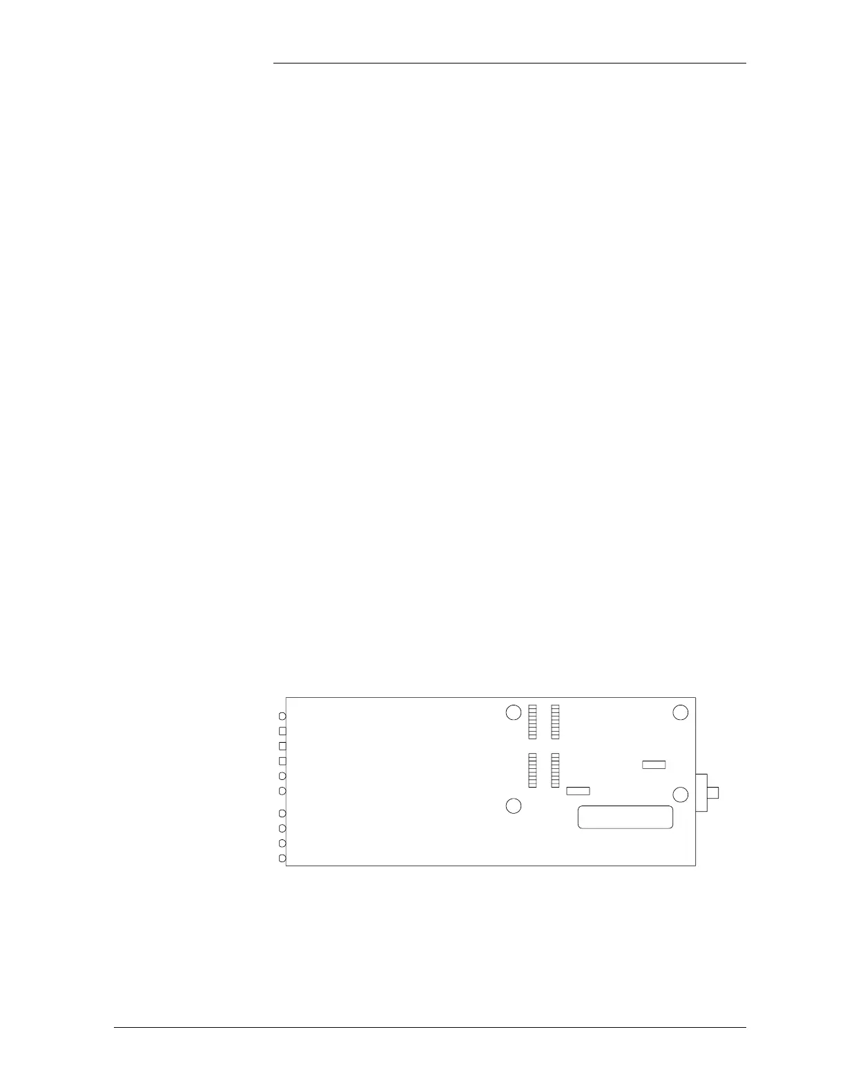
PAD Unit Setup 1. Remove the four Phillips screws from the bottom of the PAD unit.
2. Locate the battery holder on the CPU (main) circuit board and
install the battery in the orientation shown in Figure D-2. The
battery is not enabled unless Jumper LK14 is set (see Table D-1).
Note: Refer to manufacturer’s product manual for important safety
information about the battery.
Figure D-2: PAD CPU Board
Daughter
Board
Connectors
LK14
LK6
Battery
Power