Tyco Electronics Galaxy SC Controller J85501F-1
Appendix D - 4 TL1 (Transaction Language 1) and X.25 Interface Issue 13 February 2001
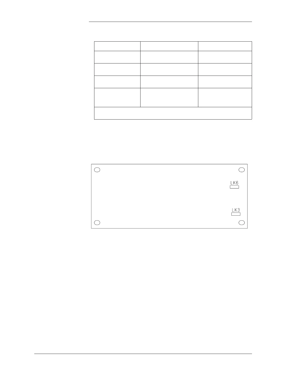
3. Verify and set the jumpers on the CPU and daughter boards as
shown in Table D-1. You may need to remove the daughter board
temporarily to access the jumpers. Refer to Figure D-3.
4. Reattach PAD cover and secure with screws.
Mount shelf in rack (frame):
1. Mount brackets to the shelf using hardware provided. The brackets
may be mounted in two orientations to accommodate different
rack sizes.
2. Position the shelf in the rack and secure using the hardware
provided.
Table D-1: Pad Jumper Settings
Jumper Location Jumper Setting* Function
LK6 (CPU) Position 1 jumpered Port 2 +12V power
LK3 (Daughter) Position 3 jumpered Port 3 +12V power
LK6 (Daughter) Position 3 jumpered Port 4 +12V power
LK14 (CPU) Jumpered
Backup Battery
Enabled
*Ports STP, X.25 and 5 do not have a power jumper setting.
Figure D-3: PAD Daughter Board