Tyco Electronics Galaxy SC Controller J85501F-1
Issue 13 February 2001 Installation 3 - 47
4. To connect additional modules to an existing installation, first
power down the BJJ Intelligent side power pack. Move the Bus
Termination Resistor assembly from the OLD last equipped
module to the NEW last equipped module when making the final
serial bus connection to the OLD last equipped module. The
modules on the bus being modified may become inactive during
the modification. They will recover automatically when the bus
and termination resistor are restored. Restore the BJJ Intelligent
power pack to service when finished.
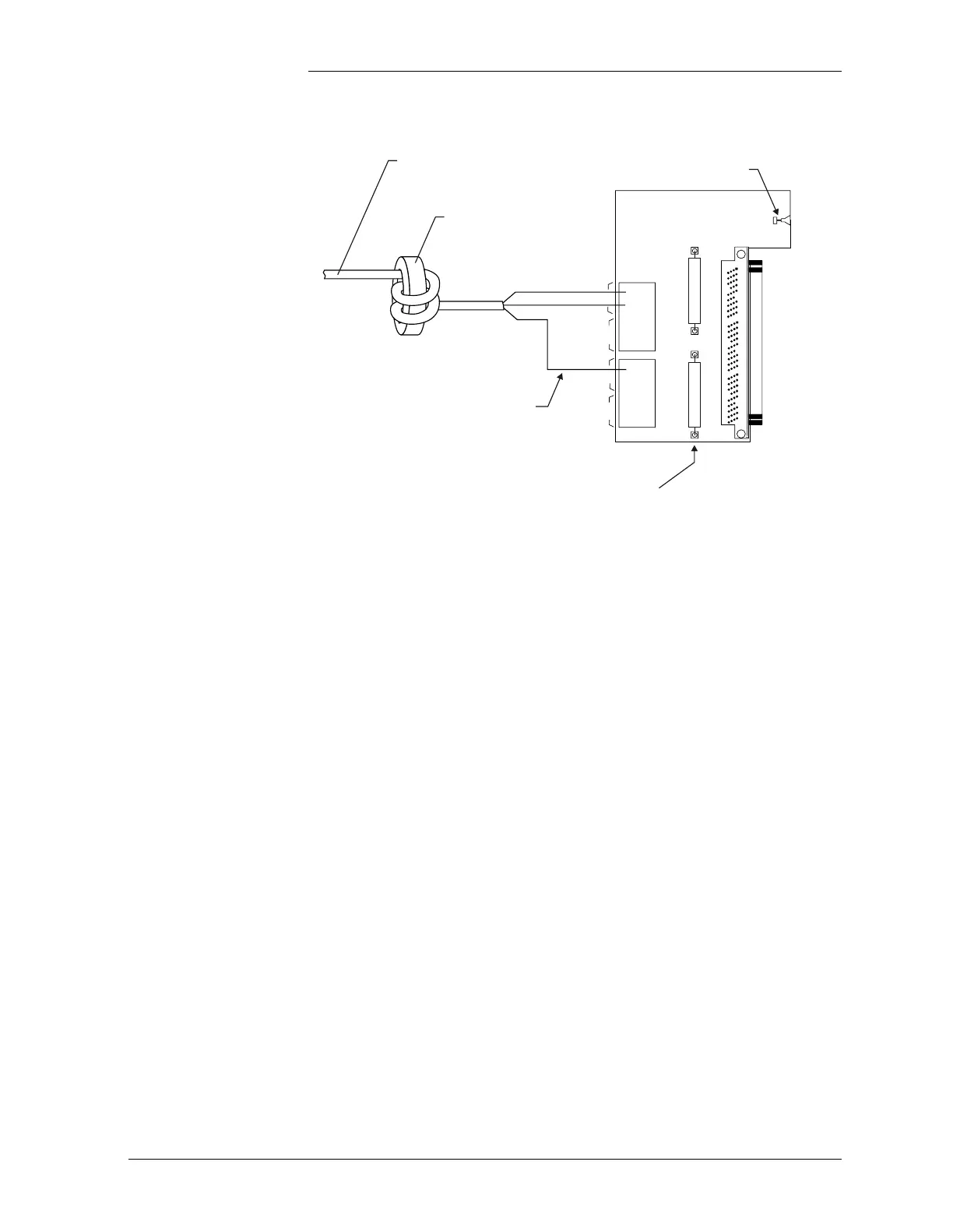
5. Wrap each bus wire twice through one of the supplied inductor
beads. Place the bead as close to the controller as possible.
Connect the bus wiring to the appropriate terminations on the
Remote Peripheral Monitoring interface card. Refer to Figure
3-14.
6. Refer to Section 3, Circuit Pack Addition/Removal/Replacement,
for information on adding the BJM pack into the chosen slot on
the Intelligent side of the card cage.
Figure 3-14: Connecting Remote Peripheral Interface
Bus Wiring to Galaxy SC Controller
4
4
1
Bus 2
Bus 3
1
Bus 2
Bus 1
Bus 3
Shield
Inductor Bead
Cable Assembly*
From first RPM module in
Bus 1 chain - TB102 (In)
Shield Wire
To Galaxy
Backplane
Secure to backplane
using screw provided
560 Ohm Resistors
Should be installed for unused
buses. Remove appropriate
resistor to use bus. Use Bus 1 first.
RPM communication bus wire must be
shielded twisted pair as per comcode
407377704 (BL/W stranded + shield)
*