Tyco Electronics Galaxy SC Controller J85501F-1
Issue 13 February 2001 Installation 3 - 39
slot chosen for the Data Switch BJK circuit pack and secure with
the mounting screw provided on the card. Refer to Figure 2-2 for
backplane mounting locations.
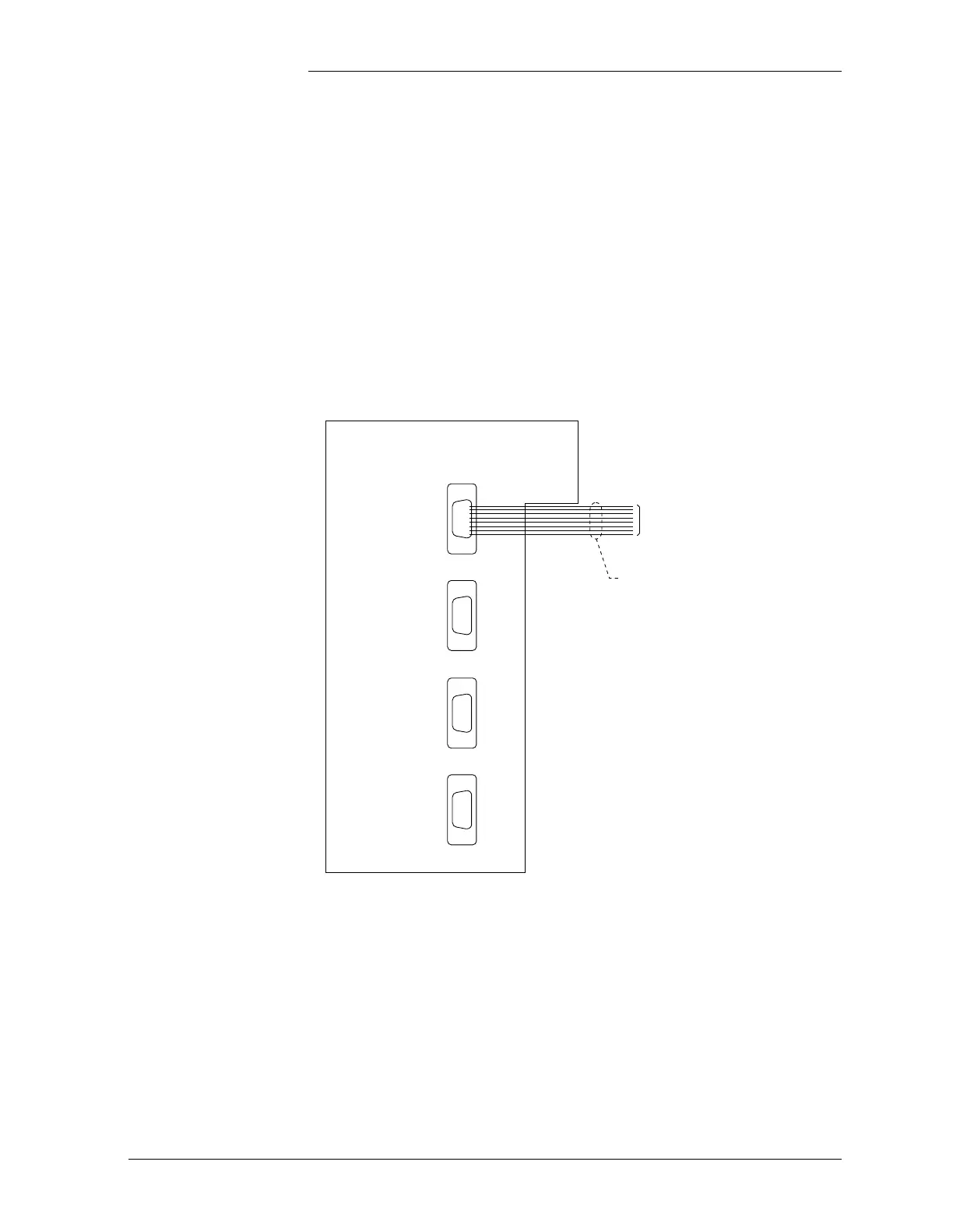
2. The Data Switch Interface card contains four DB9, 9-pin serial
port plugs for wiring to the connecting devices. See Figure 3-8 and
Table 3-J. Complete wiring from this interface to the connected
RS232 device(s) as shown in Figures 3-9, 3-10, 3-11, and 3-12.
3. Refer to Section 3, Circuit Pack Addition/Removal/Replacement,
for information on adding the BJK pack into the chosen slot on the
Intelligent side of the card cage.
Figure 3-8: Data Switch Interface Card
Data Switch Port Interface
Port4
Port3
Port2
Port1
Cable Assembly
847540416
(4 cable assemblies supplied
with the data switch option.)
To Selected
Equipment