Tyco Electronics Galaxy SC Controller J85501F-1
Issue 13 February 2001 Installation 3 - 17
2. Verify proper polarity, then run and connect the power, regulation
and shunt leads (DB, DG, DG2, RB, RG, SH-, SH+) to the TB1
terminal block or to the butt splices of the pigtail wire set
(comcode 847411824), which is provided (loose) to ease dressing
and securing these leads. Pass the terminal side of the leads on the
pigtail wire set through the hole in the right side of the Galaxy SC
enclosure and fasten them to the appropriate terminals of TB1 on
the BJF Fuse/Termination board. See Figure 3-2.
3. Connect the power and regulation leads to their appropriate bus
bars as specified in the plant and job-specific documentation.
Again, verify proper polarity when making these terminations.
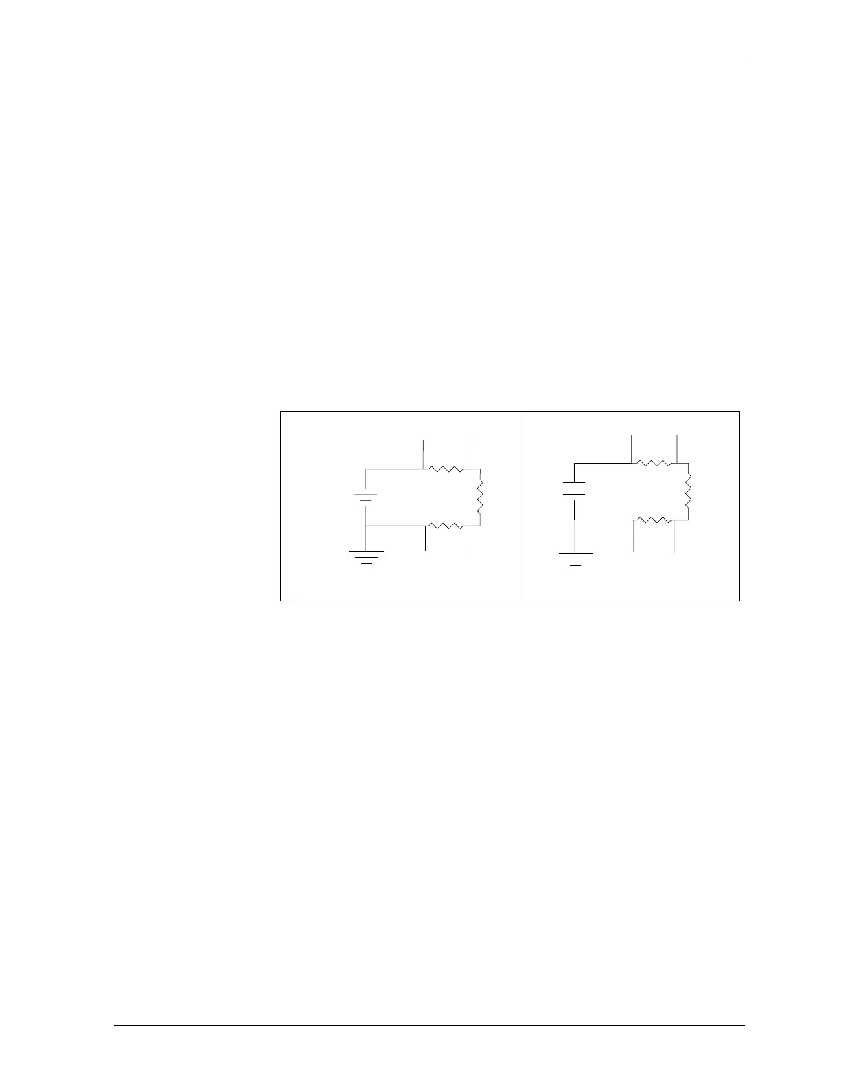
Connect the shunt pair to the plant shunt, observing polarities as
indicated in Figure 3-3.
Rectifier/Converter
Control Cables
Run and connect both ends of the rectifier/converter control cables from
each rectifier to the appropriate Rectifier Interface Module on the rear
of the Galaxy SC. See Figure 3-1. Refer to Table 3-E for a matrix of the
rectifier control cables to be used with the various Tyco Electronics
rectifiers and associated Rectifier Interface Modules. For the J85501F1
L-31, refer to Figure 3-4 for proper connector orientation information
for the three varieties of connectors which may be encountered.
The Galaxy SC can interface with up to 64 Tyco Electronics serial
rectifiers, 32 bay interface cards, and 16 converters via a serial interface
cable. If the serial rectifier bay is more than 10 cable feet from the
Galaxy SC, a 25 foot serial interconnect cable with an extension adapter
is available (Comcode 847865425). Maximum serial bus length is 200
feet.
Figure 3-3: Shunt Diagram
-24 OR -48V
SH+ SH-
SH- SH+
+24V
–
+
24V OR 48V
BATT
SH- SH+
+
–
SHUNT
IN GRD
SHUNT
IN BATT
BATT
24V
LOAD
SH+ SH-
SHUNT
IN GRD
SHUNT
IN BATT
LOAD