Tyco Electronics Galaxy SC Controller J85501F-1
Appendix D - 6 TL1 (Transaction Language 1) and X.25 Interface Issue 13 February 2001
6. Connect the RS-232/485 converter to the Galaxy RS-485 port,
located on terminal block TB4 on the rear of the controller, using
the configuration in Table D-3:
7. Connect the DB-25 Connector of the RS-232/485 converter
directly to the PAD, on the first available port, from port P2 - P5
(port 2 to port 5).
8. Connect the X.25 network phone line using an 8-pin modular jack
to the J1 port on the back of the DSU.
9. Connect the appropriate power to the DSU terminal block.
10. Connect the 3-pin power cable to the back of the PAD at the
connector labeled POWER.
11. Connect appropriate power to the PAD power cable as described
in Figure D-5.
Note: Refer to manufacturer’s instructions and safety warnings when
connecting power.
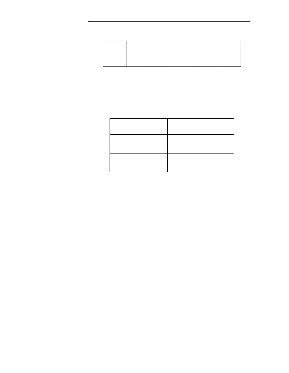
Table D-2: RS-232/485 Converter DIP Switch Settings
DIP
Switch
SW1 SW2 SW3 SW4 SW5
Mode Off On Off Off On
Table D-3: Wiring Connections From Galaxy Aux Port
TB2 to RS-232/485 Converter
Converter Wiring
Position
Galaxy Aux Port TB2
T+ T+ (top)
T- T-
R+ R+
R- R- (bottom)