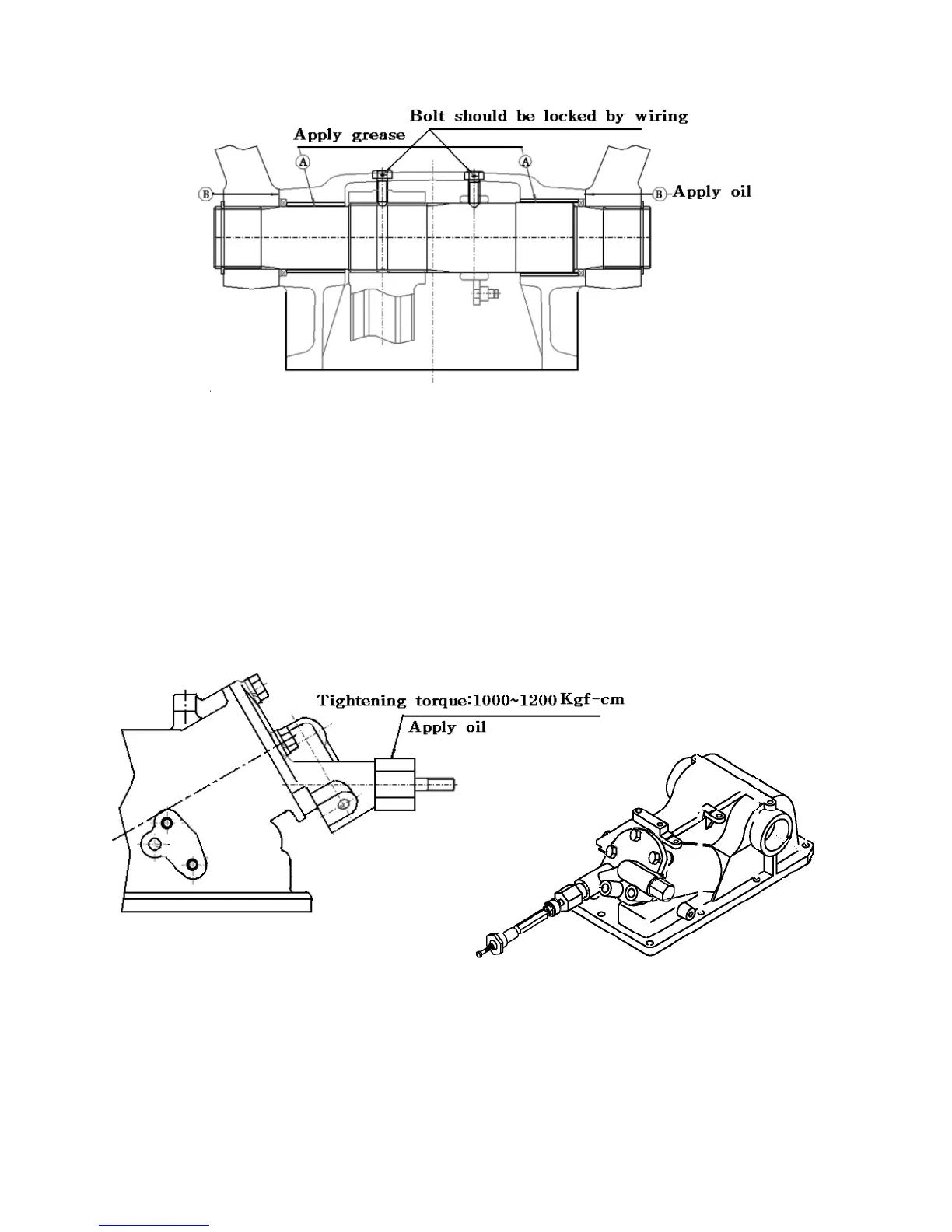
Fig.9-34.Lift arm
9) Adjust the angle of the roll bush from horizontal is 30°
10) Apply grease to the roll bush.
11) Apply grease to the cylinder case and lift arm face Which touched with each other.
12) When assemble the lift crank on the lift shaft, mesh their splines using the alignment marks
which were put there before disassembly.
13) Hex bolt (M8×20) should be locked by wiring after installation .
14) Be sure the lift shaft should be moved smoothly after installation.
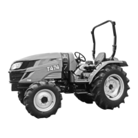
16)Rap the plug with sealing tape.
17)Tighten the slow return valve to the specified torque 1000∼1200 ㎏f-㎝ and be sure
not to damage the O-ring.
Fig. 9-35 Slow return check valve.