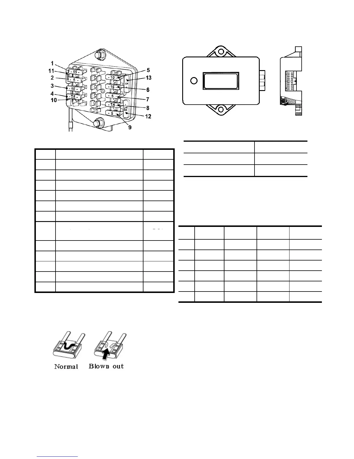
Each fuse is connected as follows
7. CONTROLLER
Fig.10-20
Capacity DC12V
Operating range DC10~16V
Operating temperature -15~80ºC
1.Function
a. Engine stop
When below condition is performed,Engine
will be stopped within 10±3 sec.( 1
st
)
Fig.10-18
1
Light / Horn 15A
2 Panel 5A
3 Turn Signal Lamp 10A
4 Working Light 7.5A
5
Hazard 10A
6
Coupler 15A
7
Controller Glow Timer 5A
10-9
The circuit has 8 blade type fuses in its
wiring circuit.When a fuse has blown
replace it with one of the same value.
Note:
Using a large capacity fuse or wire burn out
the wiring system.
Use fuse tongs to replace fuses
Fig.10-19
1 OFF ON ON ON
2 OFF ON ON OFF
3 OFF OFF ON ON
4 OFF OFF OFF ON
5 OFF OFF ON OFF
6 OFF OFF OFF OFF
Note:
When the seat S/W is Off position,engine will
stop after 3 seconds.
b. Engine Start control
Engine can be started on the condition of
Brake S/W ON ,HST S/W,and PTO S/W OFF
Position
c. Cruise control
When Cruise momentary S/W is operated as
Procedure OFF→ON→OFF.it will change the
output of Cruise magnetic.And ON output
relay will operate to light the cruise lamp.
9 Stop Lamp 5A
10 Spare -
11 Spare -
12
Spare -
13
Spare -