UPONOR CONTROL SYSTEM WIRED - INSTALLATION AND OPERATION MANUAL
14
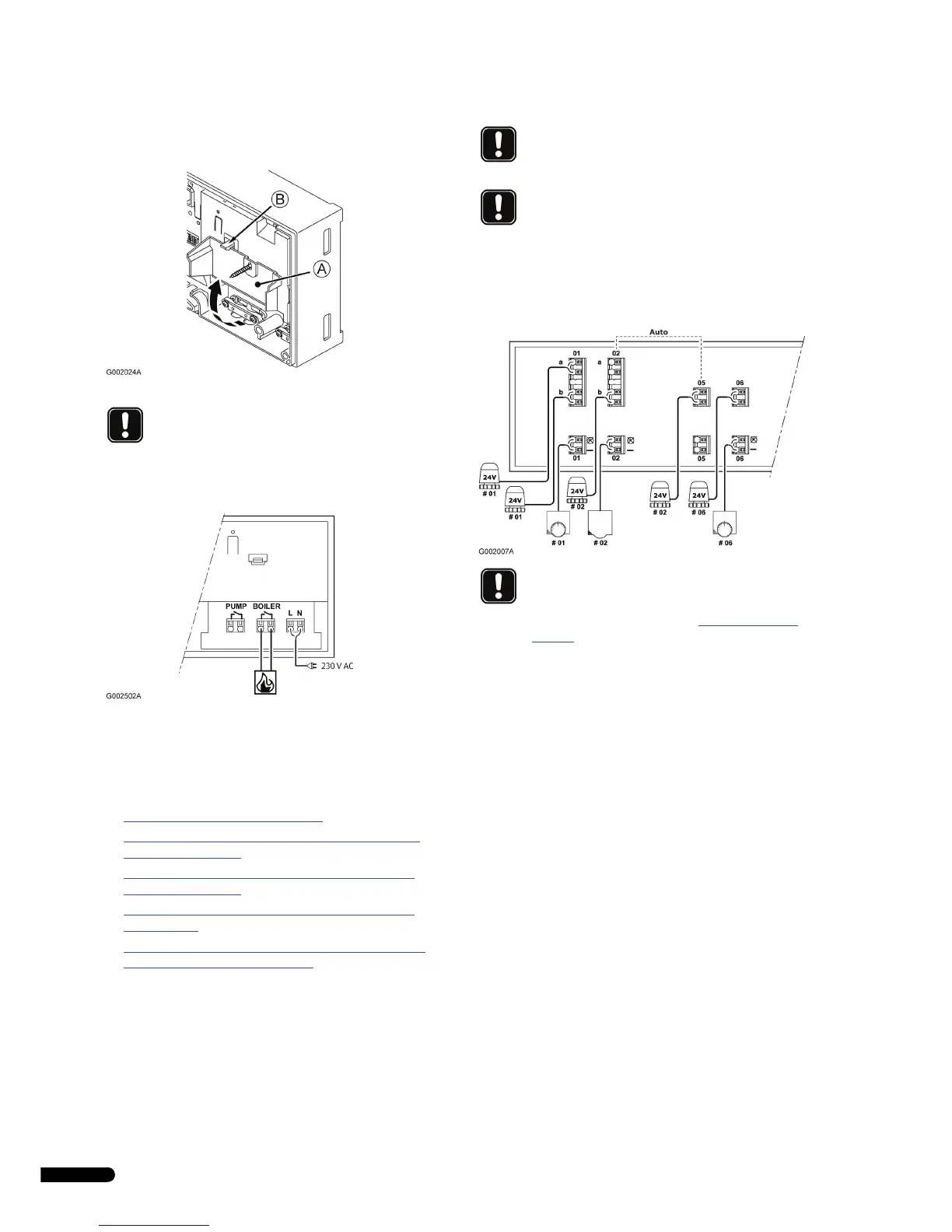
4. Open the lower lid (A) of the 230V compartment in the
controller and fix it to the latch (B)on the upper part of the
lid.
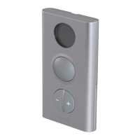
5. Connect the boiler to connectors labelled BOILER.
6. Tighten the screws of the cable clamps to fix the boiler cable.
7. Close the lid and tighten the fixing screw.
4.4 Connection examples
The following sections describe a few connection examples:
• 4.4.1 Uponor Controller C-33, page 14
• 4.4.2 Uponor Controller C-35 with three thermostats and
without timer, page 14
• 4.4.3 Uponor Controller C-35 with four thermostats and
without timer, page 15
• 4.4.4 Uponor Controller C-35 with four thermostats and
timer, page 15
• 4.4.5 Uponor Controller C-35 with four thermostats, timer
and heating–cooling switch, page 15
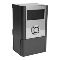
4.4.1 Uponor Controller C-33
A connection example of Uponor Controller C-33 is shown in the
figure below.
• Thermostat #01 controls the actuators on channels 01a and
01b
• Thermostat #02 controls the actuators on channels 02b, and
05
• Thermostat #06 controls the actuator on channel 06
The installation will work in a standard way with the thermostats
regulating each room according to their set temperatures.
See also the wiring diagram on the foldout page.
4.4.2 Uponor Controller C-35 with three thermostats
and without timer
A connection example of Uponor Controller C-35 using three
thermostats is shown in the figure below.
• Thermostat #01 controls the actuators on channels 01a, 01b,
02a, 02b, 03 and 04
• Thermostat #05 controls all actuators on channels 05 to 11
• Thermostat #12 controls the actuator on channel 12
The installation will work in a standard way with the thermostats
regulating each room according to their set temperatures.
See also the wiring diagram on the foldout page.
NOTE!
There is no power in the controller to supply the
boiler. The boiler connector in the controller provides
only a dry contact to switch off and on the power
connection to the boiler.
NOTE!
The timer is not available for the 6-channel
controller.
NOTE!
The economy mode (ECO) is not available for the 6-
channel controller.
NOTE!
When connecting thermostats and actuators to the
Uponor Controller, the auto-linking rules must always
be followed strictly. See section 4.3.2
Auto linking,
page 11
Any disregard to follow the auto linking rules will
result in erroneous function of the Uponor Controller.