USER’S MANUAL__________________________________________________________________
164 _________________________________________________________________ M211322EN-D
even an equal level of DC interference. Therefore, adding another 10 dB
safety margin, we get -65 dB as the recommended maximum DC gain of
the matched filter. This DC gain should be reduced even further if it is
known that coherent leakage is present in the receive signal at a level
greater than the -27 dBm worse-case A/D offset.
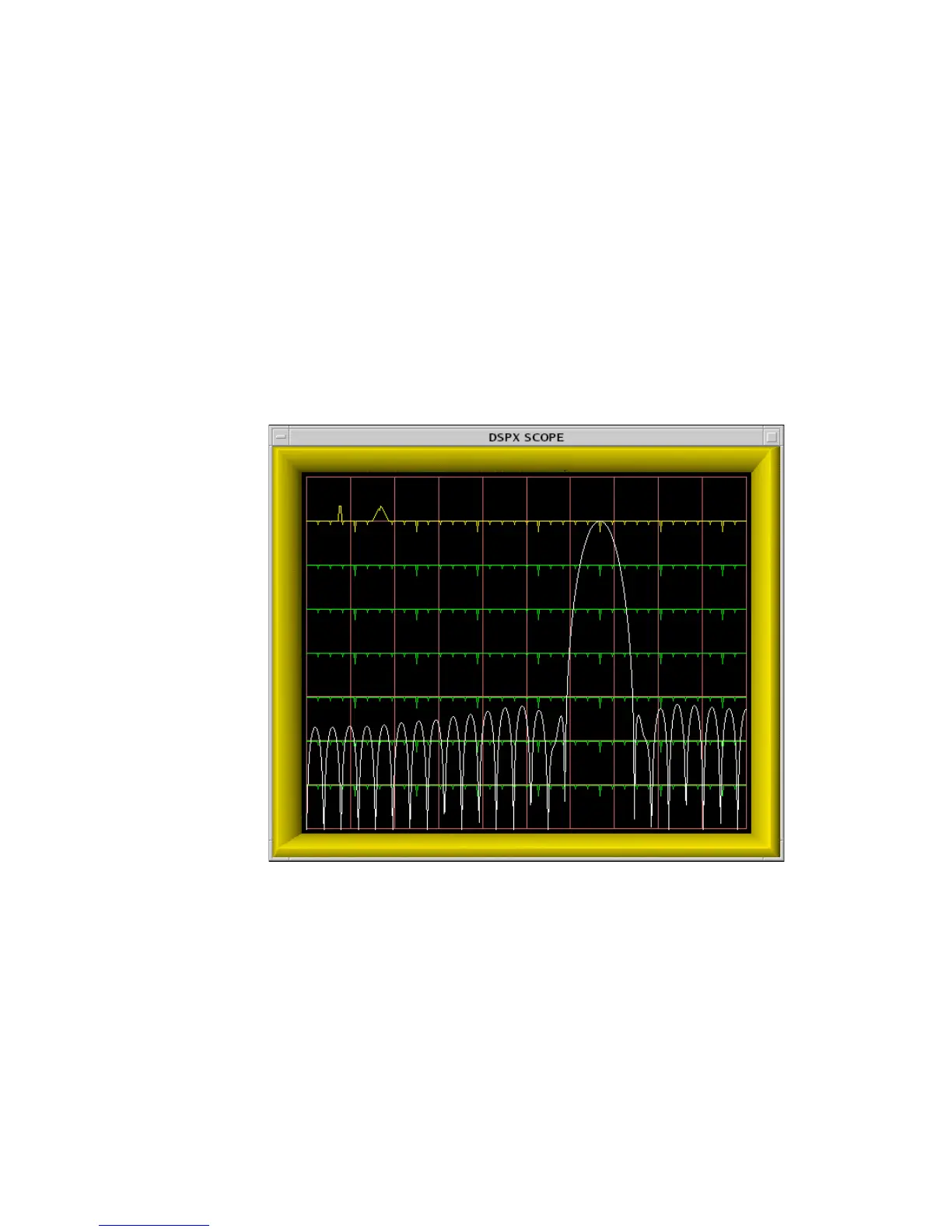
Figure 29 on page 162 shows a 60 MHz filter with particularly poor
(-42 dB) DC rejection. The frequency range of the plot is 36 MHz to
72 MHz; therefore, DC appears aliased at the right edge and we can see a
peak in the filters stopband at DC. Contrast this with the filter shown in
Figure 27 on page 149 that has a true zero at DC. In general, a poor filter
can be converted into a "nearby" good filter by making only incremental
changes to the impulse response length and/or desired bandwidth.
0916-043
Figure 29 Example of a Filter With Poor DC Rejection
 Loading...