USER’S MANUAL__________________________________________________________________
238 _________________________________________________________________ M211322EN-D
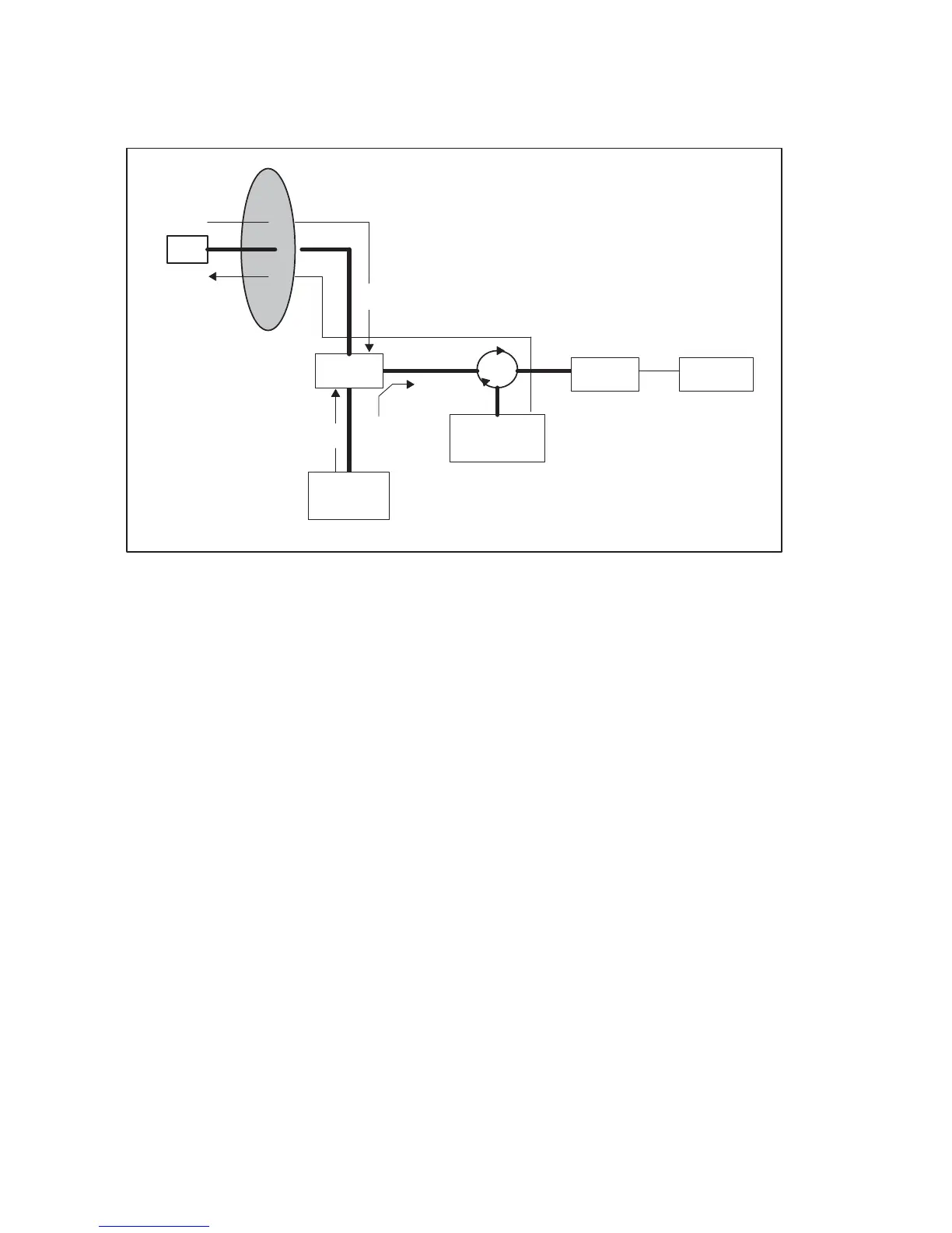
0916-062
Figure 50 Illustration of Losses that Affect LOG Calibration
6.5.4 Determination of dBZ
o
The calibration reflectivity is determined from the radar equation as
follows:
where I
o
is in mW (corrected for receive losses), the reference range r
o
is
1 km, and the radar constant C is:
where,
λ Radar wavelength in cm.
P
t
Transmitted peak power in kW.
L
t
Transmit loss (for example, 3 dB corresponds
to L
t
= 2 )
 Loading...