USER’S MANUAL__________________________________________________________________
272 _________________________________________________________________ M211322EN-D
7.4 Interface Input/Output Test (IOTEST)
This command is used to test both the input and output data busses of the
signal processor interface. When issued, the command causes sixteen
words to be read from the host controller, after which those same sixteen
words are written back out. Typically, the controller supplies a "barber
pole" input sequence consisting, for example, of successive powers of two.
If all of the output words are correct, one may conclude that there are no
malfunctioning bits in the interface hardware.
0916-098
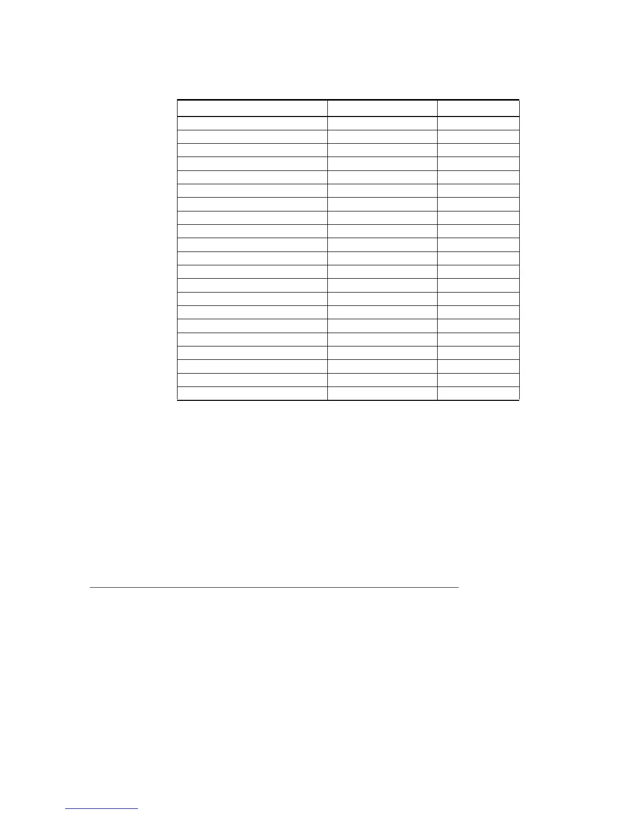
Table 13 Default Values For Operating Parameters
Parameter Scientific Units Input
Sample Size 25 pulses 25
Flag Word 0007 Hex
Log Slope 0.03 dB/LSB 1966
LOG Threshold 0.5 dB 8
CCOR Threshold 25.0 dB 400
Signal Quality Index Threshold 0.5 (dimensionless) 128
SIG Threshold 10.0 dB 160
Calibration Reflectivity 22.0 dBZ 352
Gas Attenuation 0.016 dB/km 1600
Zdr Offset (GDR) 0.0 dB 0
LDR Offset (XDR) 0.0 dB 0
AGC Integration Period 8 pulses 8
Radar Wavelength 5.3 cm. 5300
Dual PRF Filter Stabilization 10 pulses 10
UnCor Refl. Thresh. Control Flag LOG AAAA Hex
Cor Refl. Thresh. Control Flag LOG & CSR 8888 Hex
Velocity Thresh. Control Flag SQI & CSR C0C0 Hex
Width Thresh. Control Flag SQI & CSR & SIG C000 Hex
Zdr Refl. Thresh. Control Flag LOG AAAA Hex
AZ/EL Angle Offsets 0 degrees 0000 Hex
Altitude of radar 0 meters MSL 0
15 14 13 12 11 10 9 8 7 6 5 4 3 2 1 0
| | | | | | | | | | | | | | | | |
| | 0 0 0 1 1 | Command
|___________________________________________|___________________|
 Loading...